10.5.1 Overview
This example considers the equipment box shown in Figure 10-4.

Figure description:
- Overall Geometry: Square equipment mounting box with four mounting feet.
- Total Width: 300.
- Total Height: 300.
- Center of Gravity (CG Position: Indicated by a quartered circle symbol, located at a horizontal distance of 150 from the right edge and a vertical distance of 150 from the bottom edge.
- Mounting Hole Spacing: The horizontal distance between the centers of the bottom mounting feet is 285.
- Key Entities:
- Four mounting feet (indicated by small rectangles with crosshairs.
- Center of Gravity symbol (quartered circle.
- Dimension lines and numeric values (300, 150, 285.
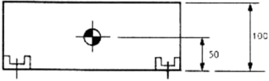
Figure description:
The provided image contains the following information:
Entities:
- Main Body: A rectangular box.
- Center of Mass Symbol: A circle with alternating black and white quadrants and crosshairs located within the box.
- Mounting Points: Two U-shaped brackets with vertical centerline markers at the bottom corners.
Dimensions:
- Total Height: 100 (indicated by a double-headed arrow on the right.
- Center of Mass Height: 50 (indicated by a dimension line from the bottom edge to the horizontal crosshair of the center of mass symbol.
Figure 10-4 - Equipment Mounting Box Geometry
The box is to operate in a space environment as follows:
- • Mass including contents: 5kg
- • Fastener size to be used: M4
- • Maximum acceleration: 20g into the base of the box.
- • Heat to be dissipated: 5W
- • Maximum allowable equipment temp: 70°C
- • Maximum ambient temp: 45°C
- • Pull out strength of insert joints: 400 N
- • Shear out strength of insert joints: 2 kN
- • Box and panel material: Aluminium 2024-T4
- • Feet dimensions: 30 mm x 20 mm x 3mm thick
10.5.2 Initial Assumptions
The feet of the box each have a single fastener loaded to 65% of yield. The four fasteners experience the following tensile forces due to the box’s inertia under acceleration:
Inertia force = mass x acceleration = 5 x 20 x 9,81 = 981N
Therefore, the load per fastener is 981/4 = 245N
An M4 x 0.7 fastener with 8,8 grade steel has the following properties:
| Nominal diameter (d) | 4 mm |
|---|---|
| Pitch (p) | 0,7 mm |
| Yield strength ( σy ) | 640 MPa |
| d2 (Equation [5.4.1]) | 3,545 mm |
| d3 (Equation [5.4.2]) | 3,141 mm |
| ds (Equation [5.4.3]) | 3,343 mm |
| As (Equation [5.4.7]) | 8,779 mm² |
The yield load of the fastener is calculated with the stress area,
The applied load to the fastener is only 4.3% of this yield strength. Therefore, low duty criteria apply (see Section 10.4) so no further strength checks need to be performed for the fastener.
The load acting on the inserts is below their pull out strength.