8.1.1 Overview
In the case of an eccentrically fastened joint, such as shown in Figure 8-1, there are three important axes:
- • the joint axis (O-O)
- • the fastener axis (S-S)
- • the axis of the external axial load (A-A)
The relative positions of these axes are defined two variables; the clamping eccentricity, s, and the loading eccentricity, a (see Figure 8-1).
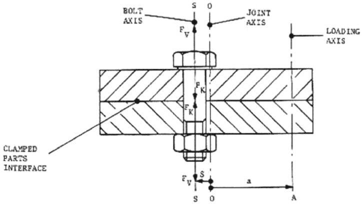
Figure description:
Labels and Axes:
- Bolt Axis (S-S: Vertical axis passing through the center of the bolt.
- Joint Axis (O-O: Vertical axis offset from the bolt axis.
- Loading Axis (A: Vertical axis indicating the line of external load application.
- Clamped Parts Interface: The horizontal contact surface between the two joined plates.
Variables and Dimensions:
- s: Horizontal distance between the Bolt Axis (S and the Joint Axis (O.
- a: Horizontal distance between the Joint Axis (O and the Loading Axis (A.
Forces:
- : Forces applied along the bolt axis (S-S.
- : Clamping forces acting between the plates.
Physical Entities:
- Bolt Assembly: Includes a hexagonal bolt head, shank, and nut.
- Clamped Parts: Two rectangular, cross-hatched plates positioned between the bolt head and nut.
Figure 8-1 - A Typical Eccentric Joint
During assembly the fastener can be pretensioned causing an interface clamping pressure with a peak at (or near) the fastener axis (S-S) as shown in Figure 8-2. The joint axis (O-O) is defined to lie at the centroid of the interface pressure distribution. For eccentrically clamped joints the joint axis does not necessarily coincide with the fastener axis.

Figure description:
- Text: "E CSS"
- Design: Italicized white "E" inside a white parallelogram with a purple border, followed by a purple parallelogram containing white "CSS" text.
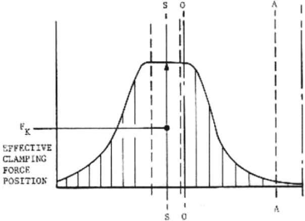
Figure description:
Clamping Force Distribution Diagram
Effective Clamping Force Position Curve
Annotations
- S (vertical_line - position: x ≈ 55)
- O (vertical_line - position: x ≈ 62)
- A (vertical_line - position: x ≈ 92)
- FK (horizontal_line - position: y ≈ 40)
- EFFECTIVE CLAMPING FORCE POSITION (text_label - position: y-axis area)
| Position (normalized 0-100) | Clamping Force (arbitrary units) |
|---|---|
| 0 | 10 |
| 10 | 12 |
| 20 | 18 |
| 30 | 30 |
| 40 | 58 |
| 45 | 78 |
| 48 | 80 |
| 55 | 80 |
| 62 | 80 |
| 65 | 72 |
| 70 | 40 |
| 80 | 20 |
| 90 | 13 |
| 100 | 11 |
Notes: The image depicts a force distribution curve with key positions labeled S, O, and A. A specific force level, FK, is indicated by a horizontal line intersecting the curve at position S. The curve shows a plateau of maximum force between the positions preceding S and following O.
Figure 8-2 - Interface Pressure Distribution after Preloading
As the external eccentric tensile load is applied the reaction under the fastener head the centroid of interface pressure (joint axis) moves away as indicated in Figure 8-3 and Figure 8-4. At the same time the centroid of the under-head reaction, , moves towards the external load.
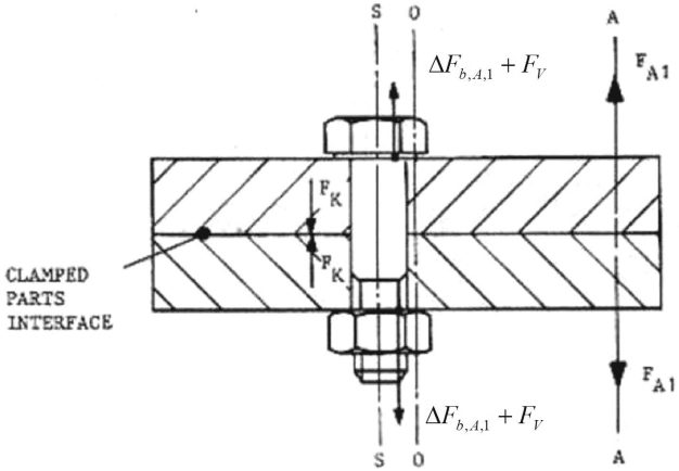
Figure description:
The image depicts a diagram of a bolted joint assembly with various force vectors and labels:
- Components: A bolt with a hexagonal head and nut clamping two parts together at the "CLAMPED PARTS INTERFACE."
- Vertical Axes:
- S: The central axis of the bolt.
- O: An offset axis located between axis S and axis A.
- A: The axis of the external tensile load.
- Force Vectors:
- : External tensile loads applied along axis A, pointing away from the clamped parts.
- : Reaction force vectors located along axis O, pointing away from the clamped parts.
- : Opposing internal force vectors at the clamped parts interface, adjacent to the bolt shank.
Figure 8-3 - Typical Joint Eccentrically Loaded
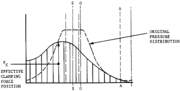
Figure description:
Pressure Distribution and Effective Clamping Force Position
Pressure Distribution Comparison
Legend
- Original Pressure Distribution — color: black; symbol: Dashed line
- Modified Distribution — color: black; symbol: Solid line with vertical hatching
Annotations
- ORIGINAL PRESSURE DISTRIBUTION (text_label - position: Points to dashed line curve)
- F_K EFFECTIVE CLAMPING FORCE POSITION (text_label - position: Arrow pointing to solid curve at approximately X=2.5)
- S (vertical_line - position: x = 4.0)
- O (vertical_line - position: x = 4.5)
- A (vertical_line - position: x = 7.5)
| Relative X-axis Position | Original Pressure Distribution (Dashed Line) | Modified Distribution (Solid Line) |
|---|---|---|
| 0 | 1.0 | 2.0 |
| 1 | 2.0 | 3.5 |
| 2 | 4.0 | 5.2 |
| 3 | 7.0 | 6.0 |
| 4 | 7.0 | 5.0 |
| 5 | 7.0 | 4.0 |
| 6 | 4.0 | 2.5 |
| 7 | 2.0 | 1.5 |
| 8 | 0.5 | 0.8 |
| 9 | 0.5 | 0.3 |
| 10 | 0.5 | 0.2 |
Notes: The chart illustrates the shift and deformation of a pressure distribution curve, with key positional markers labeled S, O, and A, and the effective clamping force position indicated by an arrow.
Figure 8-4 - Redistribution of interface pressure (with force FA1 not sufficient to cause gapping)
Figure 8-5 and Figure 8-6 show a typical interface pressure distribution caused by an eccentric load sufficient to cause one-sided opening of the joint. Such separation occurs if the axial load FA, 2 exceeds a certain value, which is dependent on the preload and the eccentricities, s and a. One-sided opening of the joint interface causes substantial increase in the fastener stress. This is discussed in Section 8.4 (see also References 8.1 and 8.2).
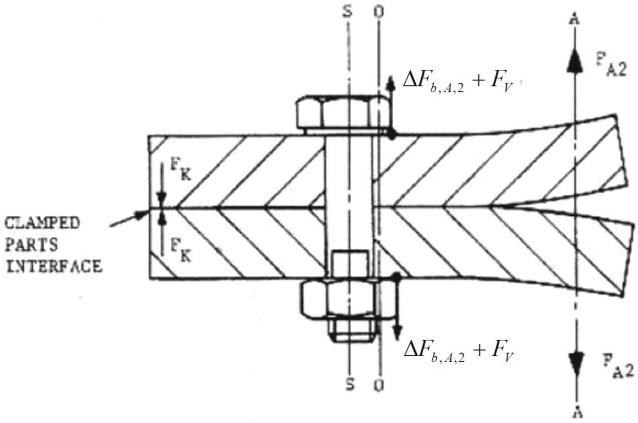
Figure description:
Entities:
- Clamped parts interface: Two diagonal-hatched plates joined by a bolt and nut assembly.
- Fastener: A hexagonal-head bolt and matching hexagonal nut.
Labels and Forces:
- : External axial load applied along vertical axis "A" at a distance from the bolt centerline.
- : Forces acting on the bolt, shown near the bolt head and nut along vertical axis "O".
- : Opposing interface forces shown at the far left side of the clamped parts.
- Axis S: Centerline of the bolt.
- Axis O: A vertical axis parallel to the bolt centerline, located at the edge of the bolt head/nut.
- Axis A: Vertical axis along which the eccentric load is applied.
Visual Features:
- Gapping: The right side of the clamped parts interface is separated, indicating joint opening.
- Hatching: Diagonal lines indicating cross-sections of the clamped material.
Figure 8-5 - An Eccentrically Loaded Joint with Gapping
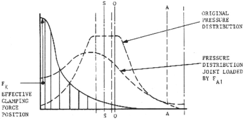
Figure description:
Pressure Distribution and Clamping Force Position Analysis
Pressure Distribution and Clamping Force Diagram
Legend
- ORIGINAL PRESSURE DISTRIBUTION — symbol: Dashed line with plateau
- PRESSURE DISTRIBUTION JOINT LOADED BY F_A1 — symbol: Long dashed bell curve
- EFFECTIVE CLAMPING FORCE POSITION — symbol: Solid line with vertical shading
Annotations
- S (vertical_line - position: x = 38)
- O (vertical_line - position: x = 45)
- A (vertical_line - position: x = 78)
- F_K EFFECTIVE CLAMPING FORCE POSITION (text_label - position: x = 0)
| Relative Position (X) | Original Pressure Distribution | Pressure Distribution Joint Loaded by F_A1 | Effective Clamping Force Distribution |
|---|---|---|---|
| 0 | 5 | 15 | 95 |
| 10 | 10 | 25 | 40 |
| 20 | 15 | 40 | 20 |
| 30 | 40 | 60 | 10 |
| 35 | 80 | 55 | 8 |
| 38 (S) | 80 | 50 | 7 |
| 45 (O) | 80 | 35 | 5 |
| 55 | 40 | 25 | 3 |
| 70 | 10 | 10 | 1 |
| 78 (A) | 5 | 5 | 0.5 |
| 90 | 2 | 2 | 0.1 |
| 100 | 0 | 0 | 0 |
Notes: The diagram illustrates how pressure distributions change when a joint is loaded, specifically identifying the effective clamping force position (F_K and key reference points S, O, and A along the horizontal axis.)
The joint indicated in Figure 8-1, Figure 8-3 and Figure 8-5 has flange contact surfaces that are relatively wide compared to the fastener diameter. Such joints are referred to as ‘Joints With Large Areas of Contact’, and the compliance equations are provided in Section 8.2.1.
Joints that employ a gasket, seal or sealing ring which is narrow with respect to the flange width, and with a flange that is stiff enough to prevent contact elsewhere on the interface surface, are referred to as ‘Cantilevered Flange Joints’ (see Figure 8-17). For such joints the interface pressure distribution does not significantly change with FA and the compliance equations are given in Section 8.3.
8.1.2 Prying
In joints with eccentric loads, the fastener load increment due to the action of the external load is greater than that of the equivalent concentric joint. This effect is often called prying or prising. Reference 8.3 provides some analytical methods and examples of this effect.

Figure description:
- Text: "E CSS"
- Color: White lettering on a dark blue/purple background.
- Shape: The background is a parallelogram.
- Entity: ECSS logo.