F-4.1 Simple Connections
Simple connections are assumed to transfer only shear at some nominal eccentricity and typically used in frames up to about five stories in height, where strength rather than stiffness govern the design. In such frames
separate lateral load resisting system is to be provided in the form of bracings or shear walls. The connections shown in Fig. 32 (A), (B), (C) and (D) can be assumed as simple connections in framed analysis and need to be checked only for the transfer of shear from beam to column.
F-4.2 Rigid Connections
In high-rise and slender structures, stiffness requirements may warrant the use of rigid connections. Rigid connections transfer significant moments to the columns and are assumed to undergo negligible deformations at the joint. These are necessary in sway frames for stability and also contribute in resisting lateral loads. The connections shown in Fig. 32 (E), (F), (G) can be assumed as rigid connection in frame analysis and need to be checked for both shear and moment transfer from beam to the column. Fully welded connections can also be considered as rigid beam to column connections.
F-4.3 Semi-rigid Connections
Semi-rigid connections fall between the two types mentioned above. The fact is that simple connections do have some degree of rotational rigidity as in the semi-rigid connections. Similarly rigid connections do experience some degree of joint deformation and this can be utilised to reduce the joint design moments.
The moment-rotation relationship of the connections have to be determined based on experiments conducted for the specific design or based on the relationship derived from tests, presented in specialist literature. The simplest method of analysis will be to idealize the connection as an equivalent rotational spring with either a bilinear or non-linear moment-
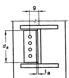
Figure description:
Key Entities and Information:
- Subject: 32A Single Web Angle connection.
- Structural Components: Shows a vertical web angle connected to the web of a horizontal beam section.
- Fasteners: Four circular bolt holes aligned vertically on the web angle.
- Dimensions:
- : Total vertical depth/length of the web angle.
- : Horizontal gauge distance from the bolt centerline to the back of the angle.
- : Thickness of the web angle leg.
32A Single Web Angle
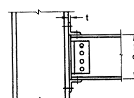
Figure description:
- Type: Technical structural diagram of a beam-to-column connection (32C.
- Key Entities:
- Vertical column (wide flange/I-beam section.
- Horizontal beam (wide flange/I-beam section.
- Single web angle with four bolts/fasteners.
- Top and bottom flange seat angles.
- Annotation: Dimension t indicates the thickness of the column flange or the connecting angle leg.
32C Top and Seat Angle with Double Web Angle
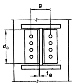
Figure description:
Entity: Double Web Angle structural connection.
Key Dimensions:
- : Depth of the connection angles.
- : Gauge distance between the centerlines of the bolt holes.
- : Thickness of an individual angle leg.
Details:
- Two angles attached to a central beam web.
- Each angle features four bolt holes arranged vertically.
32B Double Web Angle
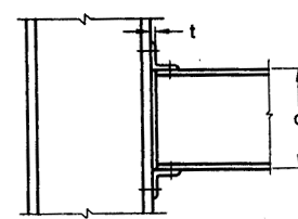
Figure description:
Technical schematic of a Top and Seat Angle structural steel connection (without web angles.
- Vertical Member: Column or girder flange.
- Horizontal Member: Beam with depth d.
- Top Angle: Secures the top flange of the beam to the vertical member.
- Seat Angle: Supports the bottom flange of the beam.
- Dimension t: Indicates thickness of the connection angle/flange.
32D Top and Seat Angle without Double Web Angle
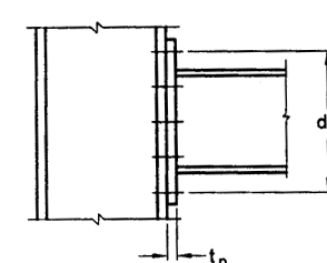
Figure description:
- Subject: Structural steel end plate connection (likely corresponding to "32E End Plate" in the context.
- Key Entities:
- Vertical Support: Shown on the left.
- Horizontal Beam: Shown on the right.
- End Plate: Vertical plate connecting the beam to the support.
- Labeled Parameters:
- : Total depth/height of the end plate connection.
- : Thickness of the end plate.
- Details: Multiple bolt rows are indicated by horizontal hash marks through the connection interface.
32E End Plate without Column Stiffeners
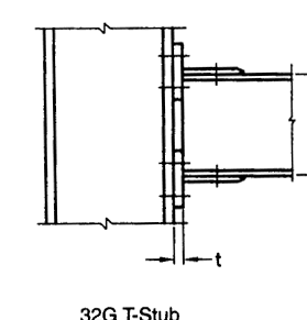
Figure description:
32G T-Stub Connection Diagram
- Main Subject: Technical drawing of a structural bolted T-stub connection.
- Key Entities:
- Vertical Member: Primary structural element (e.g., column to which the connection is made.
- T-Stub: Bolted interface component connecting horizontal members to the vertical support.
- Stiffeners: Horizontal reinforcement plates within the vertical member, aligned with the T-stub flanges.
- Dimension t: Indicates the thickness of the T-stub flange.
- Fasteners: Multiple bolts securing the T-stub to the vertical member.
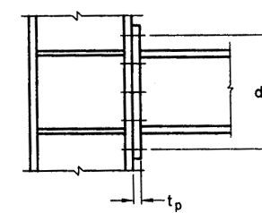
Figure description:
- Title: 32F End Plate with Column Stiffeners
- Key Entities:
- Beam: Horizontal member on the right.
- Column: Vertical member on the left.
- End Plate: Vertical plate connecting the beam to the column flange.
- Column Stiffeners: Horizontal plates within the column web, aligned with the beam flanges.
- Bolts: Fasteners shown connecting the end plate to the column flange.
- Dimensional Notations:
- : Total depth of the beam (including the end plate extensions.
- : Thickness of the end plate.
32F End Plate with Column Stiffeners
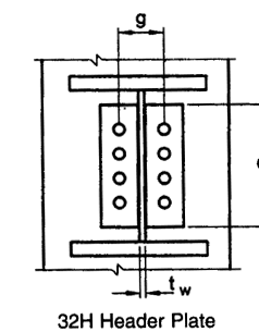
Figure description:
32H Header Plate Connection
- Key Entities:
- Web: Central vertical component with thickness .
- Flanges: Top and bottom horizontal members.
- Header Plates: Two vertical plates attached to the web.
- Bolts: Two vertical rows of four bolts each.
- Dimensional Parameters:
- (Gauge: Horizontal distance between the centerlines of the bolt rows.
- : Thickness of the central web.
FIG. 32 SIZE PARAMETER FOR VARIOUS TYPES OF CONNECTION
rotation characteristics. The classification proposed by Bjorhovde combined with the Frey-Morris model can be used with convenience to model semi-rigid connections, as given in the next section.
F-4.3.1 Connection Classification
Connections are classified according to their ultimate strength or in terms of their initial elastic stiffness and Bjorhovde's classification. It is based on the non-dimensional moment parameter and the non-dimensional rotation parameter, where is the plastic rotation. The Bjorhovde's classification is based on a reference length of the beam equal to 5 times the depth of the beam. The limits used for connection classification are shown in Table 43 and are graphically represented in Fig. 33.
F-4.3.2 Connection Models
Frye-Morris has derived the following polynomial model for the moment curvature relationship of semi-rigid connections:
- where
- moment at the joint, in kN m;
- fitting constants
Table 44 shows the curve fitting constants and standardization constants for Frye-Morris Model [All size parameters in the table are in mm (see Fig. 32)].
| Sl No. | Nature of the Connection | In Terms of Strength | In Terms of Stiffness |
|---|---|---|---|
| (1) | (2) | (3) | (4) |
| i) | Rigid connection | m' ≥ 0.7 | m' ≥ 2.5θ' |
| ii) | Semi-rigid connection | 0.7 > m' > 0.2 | 2.5θ' > m' > 0.5θ' |
| iii) | Flexible connection | m' ≤ 0.2 | m' ≤ 0.5θ' |
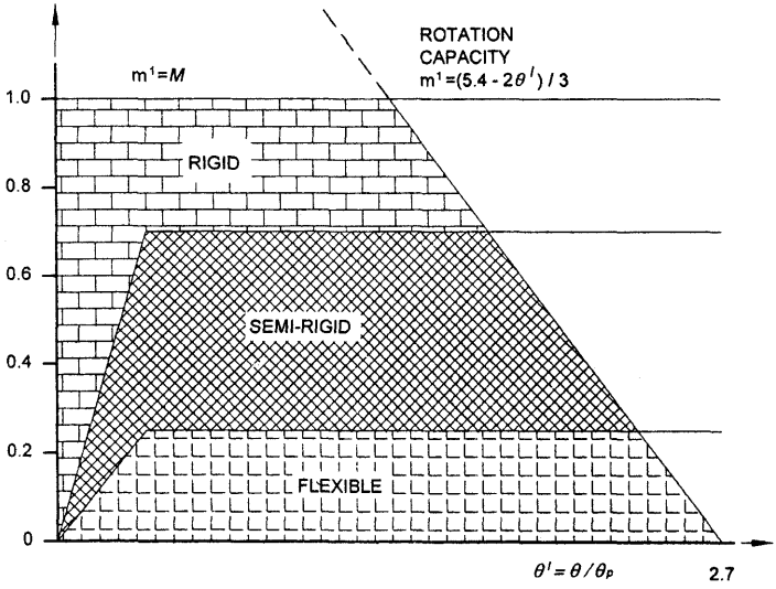
Figure description:
Moment-Rotation Classification and Capacity
Connection Classification and Rotation Capacity Chart
Legend
- RIGID — color: null; symbol: Brick pattern
- SEMI-RIGID — color: null; symbol: Cross-hatch pattern
- FLEXIBLE — color: null; symbol: L-shaped dash pattern
Annotations
- ROTATION CAPACITY m^1 = (5.4 - 2θ' / 3 (text_label - position: y = (5.4 - 2x / 3)))
- m^1 = M (text_label - position: y-axis label)
- θ' = θ / θp (text_label - position: x-axis label)
- 2.7 (text_label - position: x = 2.7)
| Stiffness Boundary A () | Stiffness Boundary B () | Rotation Capacity () | Strength Boundary () | Strength Boundary () | Strength Boundary () | |
|---|---|---|---|---|---|---|
| 0.000 | 0.00 | 0.00 | null | null | null | null |
| 0.036 | null | null | null | null | null | 0.25 |
| 0.100 | 0.70 | 0.25 | null | null | 0.70 | 0.25 |
| 0.143 | 1.00 | null | null | 1.00 | null | null |
| 0.280 | null | 0.70 | null | null | 0.70 | null |
| 0.400 | null | 1.00 | null | 1.00 | null | null |
| 1.200 | null | null | 1.00 | 1.00 | null | null |
| 1.650 | null | null | 0.70 | null | 0.70 | null |
| 2.325 | null | null | 0.25 | null | null | 0.25 |
| 2.700 | null | null | 0.00 | null | null | null |
Notes: The chart classifies structural connections based on their moment-rotation characteristics. The boundaries are defined by both stiffness (sloped lines from the origin and strength (horizontal lines at m^1 = 0.25, 0.7, and 1.0. The Rotation Capacity line provides a limit on the deformation based on the moment level.))
FIG. 33 CLASSIFICATION OF CONNECTIONS ACCORDING TO BJORHOVDE
Table 44 Connection Constants in Frye-Morris Model
(Clause F-4.3.2)
| SI No. | Type | Connection Type | Curve-Fitting Constants | Standardization Constants |
|---|---|---|---|---|
| (1) | (2) | (3) | (4) | (5) |
| i) | A | Single web angle connection | C1=1.91 × 10⁴ C2=1.30 × 10¹¹ C3=2.70 × 10¹⁷ | K = da-2.4 tc-1.81 g-0.15 |
| ii) | B | Double web angle connection | C1=1.64 × 10³ C2=1.03 × 10¹⁴ C3=8.18 × 1025 | K = da-2.4 tc-1.81 g-0.15 |
| iii) | C | Top and seat angle connection with double web angle | C1=2.24 × 10⁻¹ C2=1.86 × 10⁴ C3=3.23 × 10⁸ | K = d-1.287 ta-1.128 g-0.415 la-0.694 (g - 0.5db)1.35 |
| iv) | D | Top and seat angle connection without double web angle | C1=1.63 × 10³ C2=7.25 × 10¹⁴ C3=3.31 × 10²³ | K = d-1.5 ta-0.5 la-0.7 db-1.1 |
| v) | E | End plate connection without column stiffeners | C1=1.78 × 10⁴ C2=-9.55 × 10¹⁶ C3=5.54 × 1029 | K = de-2.4 tp-0.4 tf-1.5 |
| vi) | F | End plate connection with column stiffeners | C1=2.60 × 10² C2=5.37 × 10¹¹ C3=1.31 × 10²² | K = de-2.4 tp-0.6 |
| vii) | G | T-stub connection | C1=4.05 × 10² C2=4.45 × 10¹³ C3=-2.03 × 10²³ | K = d-1.5 tf-0.5 lt-0.7 db-1.1 |
| viii) | H | Header plate connection | C1=3.87 C2=2.71 × 10⁵ C3=6.06 × 10¹¹ | K = tp-1.6 g1.6 db-2.3 tw-0.5 |
| where | (see | Fig. 32) | tc = thickness of the web angle, in mm | |
| d = | depth | of beam | tf = thickness of flange T-stub connector, in mm | |
| da = | depth | of the angle, in mm | tw = thickness of web of the beam in the connection, in mm | |
| db = | diameter | of the bolt, in mm | tp = thickness of end plate, header plate, in mm | |
| de = | center-to-centre | of the outermost bolt of the end plate connection, in mm | la = length of the angle, in mm | |
| g = | gauge | distance of bolt line | lt = length of the T-stub connector, in mm | |
| ta = | thickness of the top angle, in mm | |||
NOTE — For preliminary analysis using a bilinear moment curvature relationship, the stiffness given in Table 45 may be assumed depending on the type of connection. The values are based on the secant stiffness at a rotation of 0.01 radian and typical dimension of connecting angle and other components as given in the table.
Table 45 Secant Stiffness
(Table 44)
| Sl No. | Type of Connection | Dimension mm | Secant Stiffness kNm/radian |
|---|---|---|---|
| (1) | (2) | (3) | (4) |
| i) | Single web connection angle | da=250, ta=10, g=35 | 1 150 |
| ii) | Double web-angle connection | da=250, ta=10, g=77.5 | 4 450 |
| iii) | Top and seat angle connection without double web angle connection | da=300, ta=10, la=140, db=20 | 2 730 |
| iv) | Header plate | dp=175, tp=10, g=75, tw=7.5 | 2 300 |