10.4.1
In friction grip type bolting, initial pretension in bolt (usually high strength) develops clamping force at the interfaces of elements being joined. The frictional resistance to slip between the plate surfaces subjected to clamping force opposes slip due to externally applied shear. Friction grip type bolts and nuts shall conform to IS 3757. Their installation procedures shall conform to IS 4000.
Design for friction type bolting in which slip is required
10.4.2
Where slip between bolted plates cannot be tolerated at working loads (slip critical connections), the requirements of 10.4.3 shall be satisfied. However, at ultimate loads, the requirements of 10.4.4 shall be satisfied by all connections.
10.4.3 Slip Resistance
to be limited, a bolt subjected only to a factored design shear force, in the interface of connections at which slip cannot be tolerated, shall satisfy the following:
where
- nominal shear capacity of a bolt as governed by slip for friction type connection, calculated as follows:
where
- coefficient of friction (slip factor) as specified in Table ,
- for fasteners in clearance holes
- = 0.85 for fasteners in oversized and short slotted holes and for fasteners in long slotted holes loaded perpendicular to the slot,
- = 0.7 for fasteners in long slotted holes loaded parallel to the slot,
- (if slip resistance is designed at service load),
- = 1.25 (if slip resistance is designed at ultimate load),
- net area of the bolt at threads, and
.
NOTE — may be evaluated at a service load or ultimate load using appropriate partial safety factors, depending upon whether slip resistance is required at service load or ultimate load.
10.4.3.1 Long joints
The provision for the long joints in 10.3.3.1 shall apply to friction grip connections also.
10.4.4 Capacity after slipping,
When friction type bolts are designed not to slip only under service loads, the design capacity at ultimate load may be calculated as per bearing type connection (see 10.3.2 and 10.3.3).
NOTE — The block shear resistance of the edge distance due to bearing force may be checked as given in 6.4.
10.4.5 Tension Resistance
A friction bolt subjected to a factored tension force (Tf) shall satisfy:
where
where
ultimate tensile stress of the bolt;
- net tensile stress area as specified in various parts of IS 1367 (for bolts where the tensile stress area is not defined, shall be taken as the area at the root of the threads);
shank area of the bolt; and
partial factor of safety.
Table 20 Typical Average Values for Coefficient of Friction (μ)
(Clause 10.4.3)
| SI No. | Treatment of Surface | Coefficient of Friction, |
|---|---|---|
| (1) | (2) | µτ (3) |
| i) | Surfaces not treated | 0.20 |
| ii) | Surfaces blasted with shot or grit with any loose rust removed, no pitting | 0.50 |
| iii) | Surfaces blasted with shot or grit and hot-dip galvanized | 0.10 |
| iv) | Surfaces blasted with shot or grit and spray-metallized with zinc (thickness 50-70 µm) | 0.25 |
| v) | Surfaces blasted with shot or grit and painted with ethylzinc silicate coat (thickness 30-60 µm) | 0.30 |
| vi) | Sand blasted surface, after light rusting | 0.52 |
| vii) | Surfaces blasted with shot or grit and painted with ethylzinc silicate coat (thickness 60-80 µm) | 0.30 |
| viii) | Surfaces blasted with shot or grit and painted with alcalizinc silicate coat (thickness 60-80 µm) | 0.30 |
| ix) | Surface blasted with shot or grit and spray metallized with aluminium (thickness > 50 µm) | 0.50 |
| x) | Clean mill scale | 0.33 |
| xi) | Sand blasted surface | 0.48 |
| xii) | Red lead painted surface | 0.10 |
10.4.6 Combined Shear and Tension
Bolts in a connection for which slip in the serviceability limit state shall be limited, which are subjected to a tension force, , and shear force, , shall satisfy:
where
- applied factored shear at design load.
- design shear strength,
- design tension strength.
10.4.7
Where prying force, Q as illustrated in Fig. 16 is significant, it shall be calculated as given below and added to the tension in the bolt.
where
where
- for non pre-tensioned bolt and 1 for pretensioned bolt,
- ,
- effective width of flange per pair of bolts
- proof stress in consistent units, and
- thickness of the end plate
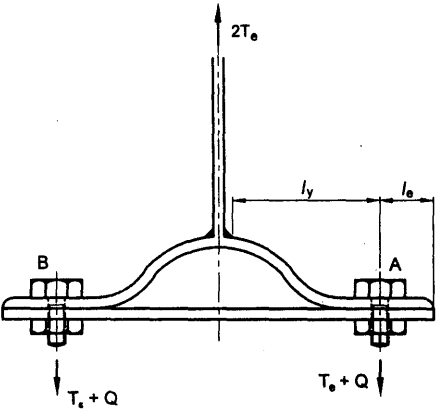
Figure description:
FIG. 16 COMBINED PRYING FORCE AND TENSION
- Entities:
- T-Section: Vertical member connected to a curved flange base.
- Bolts: Two bolts labeled A and B securing the flange to a base plate.
- Forces:
- : Upward tension force applied to the vertical member.
- : Downward force acting at each bolt, representing combined tension ( and prying force (.
- Dimensions:
- : Distance from the vertical member connection to the bolt centerline.
- : Distance from the bolt centerline to the flange edge.
FIG. 16 COMBINED PRYING FORCE AND TENSION