12.11.1
Special moment frames (SMF) shall be made of E250B steel of IS 2062 and should be shown to withstand inelastic deformation corresponding to a joint rotation of 0.04 radians without degradation in strength and stiffness below the full yield value (M p ). Special moment frames meeting the requirements of this section shall be deemed to satisfy the required inelastic deformation.
12.11.1.1
Special moment frames (SMF) may be used in any seismic zone [see IS 1893 (Part 1)] and for any buildings (importance-factor values).
12.11.2 Beam-to-Column Joints and Connections
12.11.2.1
All beam-to-column connections shall be rigid (see Annex F) and designed to withstand a moment of at least 1.2 times the full plastic moment of the connected beam. When a reduced beam section is used, its minimum flexural strength shall be at least equal to 0.8 times the full plastic moment of the unreduced section.
12.11.2.2
The connection shall be designed to withstand a shear resulting from the load combination 1.2DL + 0.5LL plus the shear resulting from the application of in the same direction, at each end of the beam (causing double curvature bending). The shear strength need not exceed the required value corresponding to the load combination in 12.2.3.
12.11.2.3
In column strong axis connections (beam and column web in the same plane), the panel zone shall be checked for shear buckling in accordance with 8.4.2 at the design shear defined in 12.11.2.2. Column web doubler plates or diagonal stiffeners may be used to strengthen the web against shear buckling.
12.11.2.4
The individual thickness of the column webs and doubler plates, shall satisfy the following:
where
- thickness of column web or doubler plate.
panel-zone width between column flanges
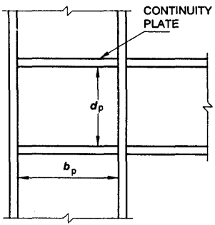
Figure description:
- Title: FIG. 21 CONTINUITY PLATES
- Key Entities:
- Continuity Plate: Horizontal reinforcement plates within the column flanges.
- Column: Vertical structural member.
- Beam: Horizontal structural member connected to the column.
- Dimensions:
- : Panel-zone width between column flanges.
- : Panel-zone depth (height between continuity plates.
FIG. 21 CONTINUITY PLATES
12.11.2.5
Continuity plates (tension stiffner) (see 8.7) shall be provided in all strong axis welded connections except in end plate connection.
12.11.3 Beam and Column Limitation
12.11.3.1
Beam and column sections shall be either plastic or compact as defined in 3.7.2. At potential plastic hinge locations, they shall necessarily be plastic
12.11.3.2
The section selected for beams and column shall satisfy the following relation:
where
sum of the moment capacity in the column above and below the beam centreline; and
In tall buildings, higher mode effects shall be accounted for in accordance with specialist literature.
12.11.3.3
Lateral support to the column at both top and bottom beam flange levels shall be provided so as to resist at least 2 percent of the beam flange strength, except for the case described in 12.11.3.4.
12.11.3.4
A plane frame designed as non-sway in the direction perpendicular to its plane, shall be checked for buckling, under the load combination specified in 12.2.3.