7.7.1 General
7.7.1.1
Compression members composed of two main components battened should preferably have the individual members of the same cross-section and symmetrically disposed about their major axis. Where practicable, the compression members should have a radius of gyration about the axis perpendicular to the plane of the batten not less than the radius of gyration about the axis parallel to the plane of the batten (see Fig. 11).
7.7.1.2
Battened compression members, not complying with the requirements specified in this section or those subjected to eccentricity of loading, applied moments or lateral forces in the plane of the battens (see Fig. 11), shall be designed according to the exact theory of elastic stability or empirically, based on verification by tests.
NOTE — If the column section is subjected to eccentricity or other moments about an axis perpendicular to battens, the battens and the column section should be specially designed for such moments and shears.
7.7.1.3
The battens shall be placed opposite to each other at each end of the member and at points where the member is stayed in its length and as far as practicable, be spaced and proportioned uniformly throughout. The number of battens shall be such that the member is divided into not less than three bays
within its actual length from centre-to-centre of end connections.
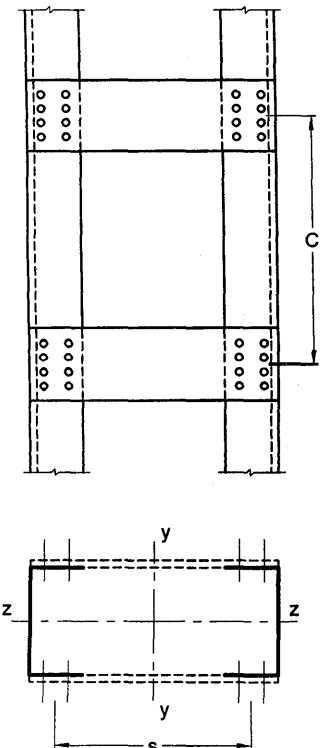
Figure description:
- Subject: Structural technical drawing of a batten column section (Fig. 11.
- Key Components:
- Two parallel vertical main members.
- Horizontal batten plates connecting the main members at regular intervals.
- Bolt/rivet patterns used for joining battens to main members.
- Key Dimensions & Labels:
- C: Center-to-center distance between the connections of consecutive batten plates.
- s: Spacing between the vertical main members in the cross-section view.
- Axes: Cross-section shows vertical symmetry axis (y-y and horizontal symmetry axis (z-z.
FIG. 11 BATTEN COLUMN SECTION
7.7.1.4
The effective slenderness ratio of battened columns, shall be taken as 1.1 times the , the maximum actual slenderness ratio of the column, to account for shear deformation effects.
7.7.2 Design of Battens
7.7.2.1 Battens
Battens shall be designed to carry the bending moments and shear forces arising from transverse shear force equal to 2.5 percent of the total axial force on the whole compression member, at any point in the length of the member, divided equally between parallel planes of battens. Battened member carrying calculated bending moment due to eccentricity of axial loading, calculated end moments or lateral loads parallel to the plane of battens, shall be designed to carry actual shear in addition to the above shear. The main members shall also be checked for the same shear force and bending moments as for the battens.
Battens shall be of plates, angles, channels, or I-sections and at their ends shall be riveted, bolted or welded to the main components so as to resist simultaneously a shear along the column axis and a moment at each connection,
where
- transverse shear force as defined above
- C = distance between centre-to-centre of battens, longitudinally;
- number of parallel planes of battens; and
7.7.2.2 Tie plates
Tie plates are members provided at the ends of battened and laced members, and shall be designed by the same method as battens. In no case shall a tie plate and its fastenings be incapable of carrying the forces for which the lacing or batten has been designed.
7.7.2.3 Size
When plates are used for battens, the end battens and those at points where the member is stayed in its length shall have an effective depth, longitudinally, not less than the perpendicular distance between the centroids of the main members. The intermediate battens shall have an effective depth of not less than three quarters of this distance, but in no case shall the effective depth of any batten be less than twice the width of one member, in the plane of the battens. The effective depth of a batten shall be taken as the longitudinal distance between outermost bolts, rivets or welds at the ends. The thickness of batten or the tie plates shall be not less than one-fiftieth of the distance between the innermost connecting lines of rivets, bolts or welds, perpendicular to the main member.
7.7.2.4
The requirement of bolt size and thickness of batten specified above does not apply when angles, channels or I-sections are used for battens with their legs or flanges perpendicular to the main member. However, it should be ensured that the ends of the compression members are tied to achieve adequate rigidity.
7.7.3 Spacing of Battens
In battened compression members where the individual members are not specifically checked for shear stress and bending moments, the spacing of battens, centre-to-centre of its end fastenings, shall be such that the slenderness ratio (KL/r) of any component over that distance shall be neither greater than 50 nor greater than 0.7 times the slenderness ratio of the member as a whole about its z-z (axis parallel to the battens).
7.7.4 Attachment to Main Members
7.7.4.1 Welded connections
Where tie or batten plates overlap the main members, the amount of lap shall be not less than four times the thickness of the plate. The length of weld connecting each edge of the batten plate to the member shall, in aggregate, be not less than half the depth of the batten plate. At least one-third of the weld shall be placed at each end of this edge. The length of weld and depth of batten plate shall be measured along the longitudinal axis of the main member.
In addition, the welding shall be returned along the other two edges of the plates transversely to the axis of the main member for a length not less than the minimum lap specified above.