The fire resistance rating of various building components such as walls, columns, beams, and floors are given in Table 31 and Table 32. Fire damage assessment of various structural elements of the building and adequacy of the structural repairs can be done by the fire resistance rating for encased steel column and beam (Table 31 and Table 32).
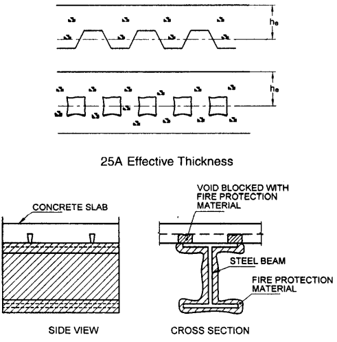
Figure description:
Key Information:
- 25A Effective Thickness: Diagrams illustrate the measurement of effective thickness ( for composite concrete slabs with profiled steel decking.
- 25B Blocking of Rib Voids: Detailed side and cross-section views of a structural steel beam supporting a concrete slab.
- Structural Components:
- Concrete Slab: Top layer of the floor system.
- Steel Beam: I-section supporting the slab.
- Fire Protection Material: Encasing the steel beam and filling the rib voids between the beam flange and the slab.
- Core Concept: Illustrates methods to achieve fire resistance ratings by protecting steel elements and blocking voids to prevent fire spread.
25B Blocking of Rib Voids
FIG. 25 THREE SIDED FIRE EXPOSURE CONDITION REQUIREMENTS
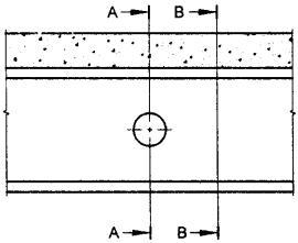
Figure description:
Subject: Fig. 25 Three-Sided Fire Exposure Condition Requirements
Key Components:
- Structural Member: A horizontal beam or joist.
- Concrete Slab: The top layer (stippled texture, providing protection to the top surface of the member.
- Circular Opening: A hole located in the web of the structural member.
- Section A-A: A vertical reference line passing through the center of the circular opening.
- Section B-B: A vertical reference line passing through a solid portion of the structural member.
Context: The diagram illustrates conditions for fire exposure where the top surface is shielded (likely by the concrete, leaving the bottom and two sides exposed.
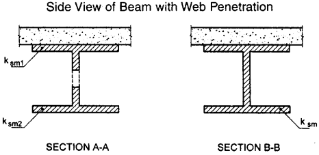
Figure description:
Diagram: Side View of Beam with Web Penetration
- Section A-A: Shows a cross-section of an I-beam with a penetration (hole in the vertical web.
- : Label for the top flange.
- : Label for the bottom flange.
- Section B-B: Shows a solid cross-section of the I-beam without web penetration.
- : Label for the bottom flange.
- Common Entities: Both sections show the steel beam attached to an overhead concrete slab.
FIG. 26 WEB PENETRATION
Table 31 Encased Steel Columns, 203 mm x 203 mm
(Protection Applied on Four Sides)
(Clause 16.11)
| SI No. | Nature of Construction and Materials | Minimum Dimensions Excluding Any Finish, for a Fire Resistance of mm | ||||
|---|---|---|---|---|---|---|
| 1 h | 1 ½ h | 2 h | 3 h | 4 h | ||
| (3) | (4) | (5) | (6) | (7) | ||
| i) | Hollow protection (without an air cavity over the flanges): | |||||
| a) Metal lathing with trowelled lightweight aggregate gypsum plaster1) | 13 | 15 | 20 | 32 | - | |
| b) Plasterboard with 1.6 mm wire binding at 100 mm pitch, finished with lightweight aggregate gypsum plaster less than the thickness specified: | ||||||
| 1) 9.5 mm plaster board | 10 | 15 | - | - | - | |
| 2) 19 mm plaster board | 10 | 13 | 20 | - | - | |
| c) Asbestos insulating boards, thickness of board: | ||||||
| 1) Single thickness of board, with 6 mm cover fillets at transverse joints | - | 19 | 25 | - | - | |
| 2) Two layers, of total thickness | - | - | - | 38 | 50 | |
| d) Solid bricks of clay, composition or sand lime, reinforced in every horizontal joint, unplastered | 50 | 50 | 50 | 75 | 100 | |
| e) Aerated concrete blocks | 60 | 60 | 60 | - | - | |
| f) Solid blocks of lightweight concrete hollow protection (with an air cavity over the flanges) | 50 | 50 | 50 | 60 | 75 | |
| ii) | Asbestos insulating board screwed to 25 mm asbestos battens | 12 | 19 | - | - | - |
| iii) | Solid protections | |||||
| a) Concrete, not leaner than 1:2:4 mix (unplastered): | ||||||
| 1) Concrete not assumed to be load bearing, reinforced2) | 25 | 25 | 25 | 50 | 75 | |
| 2) Concrete assumed to be load bearing | 50 | 50 | 50 | 75 | 75 | |
| b) Lightweight concrete, not leaner than 1:2:4 mix (unplastered) concrete not assumed to be load bearing, reinforced2) | 25 | 25 | 25 | 25 | 25 | |