F-3.1
Where the ends of compression members are faced for bearing over the whole area, they shall be spliced to hold the connected parts aligned. The ends of compression members faced for bearing shall invariably be machined to ensure perfect contact of surfaces in bearing (see Fig. 31).
F-3.2
Where such members are not faced for complete bearing the splices shall be designed to transmit all the forces to which the member is subjected at the splice location.
F-3.3
Wherever possible, splices shall be proportioned and arranged so that centroidal axis of the splice
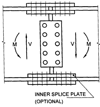
Figure description:
Title: 30A Conventional Splice (Typical
Key Components:
- Central Web Splice Plate: Features two vertical rows of five bolts/rivets (10 total.
- Flange Splice Plates: Located at the top and bottom of the structural member.
- Inner Splice Plate (Optional: Indicated as an additional layer on the bottom flange splice.
Force Indicators:
- M: Bending moments, represented by curved arrows.
- V: Shear forces, represented by vertical arrows.
30A Conventional Splice (Typical)
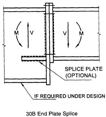
Figure description:
FIG. 30 BEAM SPLICES - 30B End Plate Splice
- Main Component: Structural beam splice using an end plate connection.
- Force Indicators:
- V: Vertical shear forces acting in opposite directions on each side of the splice.
- M: Bending moments acting in opposite directions.
- Key Features:
- Splice Plate (Optional: Horizontal reinforcement located at the beam junction.
- Lower Support/Plate: Labeled as "if required under design" at the bottom of the connection.
FIG. 30 BEAM SPLICES
coincides as nearly as possible with the centroidal axes of the members joined, in order to avoid eccentricity; but where eccentricity is present in the joint, the resulting stress considering eccentricity shall be provided for.
F-3.4
If a column flange is subjected to significant
tension or if the faces are not prepared for bearing, or if full continuity is required without slip, only HSFG bolts shall be used.
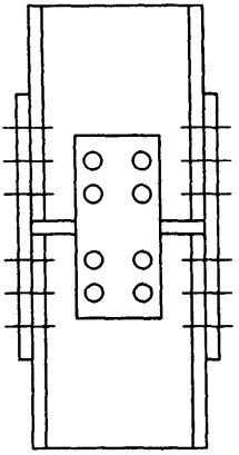
Figure description:
Technical Diagram: Typical Column Splice
- Entities: Two structural column sections joined at a horizontal interface.
- Web Splice: A central rectangular plate secured by 8 bolts (4 per column section.
- Flange Splices: Two side plates attached to the column flanges, each featuring 10 fastener indicators (5 per column section.
- Key Requirement: Per text F-3.4, HSFG (High Strength Friction Grip bolts must be used for significant tension, unprepared bearing faces, or required non-slip continuity.
FIG. 31 COLUMN SPLICE (TYPICAL)