3.7.1
Plate elements of a cross-section may buckle locally due to compressive stresses. The local buckling can be avoided before the limit state is achieved by limiting the width to thickness ratio of each element of a cross-section subjected to compression due to axial force, moment or shear.
3.7.1.1
When plastic analysis is used, the members shall be capable of forming plastic hinges with sufficient rotation capacity (ductility) without local buckling, to enable the redistribution of bending moment required before formation of the failure mechanism.
3.7.1.2
When elastic analysis is used, the member shall be capable of developing the yield stress under compression without local buckling.
3.7.2
On basis of the above, four classes of sections are defined as follows:
- a) Class 1 (Plastic) — Cross-sections, which can develop plastic hinges and have the rotation capacity required for failure of the structure by formation of plastic mechanism. The width to thickness ratio of plate elements
shall be less than that specified under Class 1 (Plastic), in Table 2.
- b) Class 2 (Compact) — Cross-sections, which can develop plastic moment of resistance, but have inadequate plastic hinge rotation capacity for formation of plastic mechanism, due to local buckling. The width to thickness ratio of plate elements shall be less than that specified under Class 2 (Compact), but greater than that specified under Class 1 (Plastic), in Table 2.
- c) Class 3 (Semi-compact) — Cross-sections, in which the extreme fiber in compression can reach yield stress, but cannot develop the plastic moment of resistance, due to local buckling. The width to thickness ratio of plate elements shall be less than that specified under Class 3 (Semi-compact),but greater than that specified under Class 2 (Compact), in Table 2.
- d) Class 4 (Slender) — Cross-sections in which the elements buckle locally even before reaching yield stress. The width to thickness ratio of plate elements shall be greater than that specified under Class 3 (Semi-compact), in Table 2. In such cases, the effective sections for design shall be calculated either by following the provisions of IS 801 to account for the post-local-buckling strength or by deducting width of the compression plate element in excess of the semi-compact section limit.
When different elements of a cross-section fall under different classes, the section shall be classified as governed by the most critical element.
The maximum value of limiting width to thickness ratios of elements for different classifications of sections are given in Table 2.
3.7.3 Types of Elements
- a) Internal elements — These are elements attached along both longitudinal edges to other elements or to longitudinal stiffeners connected at suitable intervals to transverse stiffeners, for example, web of I-section and flanges and web of box section.
- b) Outside elements or outstands – These are elements attached along only one of the longitudinal edges to an adjacent element, the other edge being free to displace out of plane, for example flange overhang of an I-section, stem of T-section and legs of an angle section.
- c) Tapered elements — These may be treated as flat elements having average thickness as defined in SP 6 (Part 1).
| Compression Element | Ratio | Class of Section | |||
|---|---|---|---|---|---|
| (1) | (2) | Class 1 Plastic (3) | Class 2 Compact (4) | Class 3 Semi-compact (5) | |
| Outstanding element of compression flange | Rolled section | b/tf | 9.4ε | 10.5ε | 15.7ε |
| Welded section | b/tf | 8.4ε | 9.4ε | 13.6ε | |
| Internal element of compression flange | Compression due to bending | b/tf | 29.3ε | 33.5ε | 42ε |
| Axial compression | b/tf | Not applicable | |||
| Web of an I, H or box section | Neutral axis at mid-depth | d/tw | 84ε | 105ε | 126ε |
| Generally | If r1 is negative: | d/tw | 84ε /(1+r1) but ≤ 42ε | 105.0ε /(1+r1) | 126.0ε /(1+2r2) but ≤ 42ε |
| If r1 is positive: | d/tw | 105.0ε /(1+1.5r1) but ≤ 42ε | |||
| Axial compression | d/tw | Not applicable | 42ε | ||
| Web of a channel | d/tw | 42ε | 42ε | 42ε | |
| Angle, compression due to bending (Both criteria should be satisfied) | b/t d/t | 9.4ε 9.4ε | 10.5ε 10.5ε | 15.7ε 15.7ε | |
| Single angle, or double angles with the components separated, axial compression (All three criteria should be satisfied) | b/t d/t (b+d)/t | Not applicable | 15.7ε 15.7ε 25ε | ||
| Outstanding leg of an angle in contact back-to-back in a double angle member | d/t | 9.4ε | 10.5ε | 15.7ε | |
| Outstanding leg of an angle with its back in continuous contact with another component | d/t | 9.4ε | 10.5ε | 15.7ε | |
| Stem of a T-section, rolled or cut from a rolled I-or H-section | D/tf | 8.4ε | 9.4ε | 18.9ε | |
| Circular hollow tube, including welded tube subjected to: | a) moment | D/t | 42ε2 | 52ε2 | 146ε2 |
| b) axial compression | D/t | Not applicable | 88ε | ||
| NOTES |
|---|
| 1 Elements which exceed semi-compact limits are to be taken as of slender cross-section. |
| 2 ε= (250 /fy)1/2. |
| 3 Webs shall be checked for shear buckling in accordance with 8.4.2 when d/t > 67ε, where, b is the width of the element (may be taken as clear distance between lateral supports or between lateral support and free edge, as appropriate), t is the thickness of element, d is the depth of the web, D is the outer diameter of the element (see Fig. 2, 3.7.3 and 3.7.4). |
| 4 Different elements of a cross-section can be in different classes. In such cases the section is classified based on the least favourable classification. |
| 5 The stress ratio r1 and r2 are defined as: r1 = Actual average axial stress (negative if tensile) --------------------------------------------------Design compressive stress of web alone r2 = Actual average axial stress (negative if tensile) --------------------------------------------------Design compressive stress of overall section |
The design of slender compression element (Class 4) considering the strength beyond elastic local buckling of element is outside the scope of this standard. Reference may be made to IS 801 for such design provisions. The design of slender web elements may be made as given in 8.2.1.1 for flexure and 8.4.2.2 for shear.
3.7.4 Compound Elements in Built-up Section (see Fig. 2)
In case of compound elements consisting of two or more elements bolted or welded together, the limiting width to thickness ratios as given in Table 2 should be considered on basis of the following:
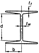
Figure description:
Entity: Rolled Beam/Column Cross-Section
Key Dimensions:
- : Internal web depth (clear distance between flanges.
- : Half-width of the flange.
- : Flange thickness.
- : Web thickness.
ROLLED BEAMS AND COLUMNS
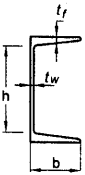
Figure description:
[ b
ROLLED CHANNELS
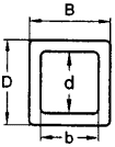
RECTANGULAR HOLLOW SECTIONS
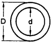
CIRCULAR HOLLOW SECTIONS
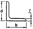
SINGLE ANGLES
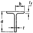
TEES
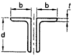
Figure description:
Entity: Double angles (back-to-back forming a T-shape.
Dimensions:
- b: Width of the horizontal flange for each angle.
- d: Total vertical depth/height of the angles.
- t: Thickness of the horizontal flange.
- Configuration: Two identical angle sections positioned symmetrically around a central vertical axis.
DOUBLE ANGLES (BACK TO BACK)
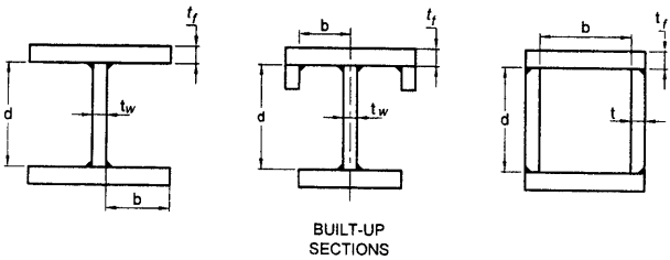
Figure description:
The image displays three diagrams of BUILT-UP SECTIONS used in structural engineering.
Key Dimensions and Notations:
- : Internal depth or height of the web/section.
- : Width or half-width of the flange/top plate.
- : Thickness of the flange or top plate.
- : Thickness of the central web.
- : Thickness of the side wall (in the box section.
Section Types:
- I-Section/Girder (Left: Composed of a central web plate welded to top and bottom flange plates.
- Modified T-Section (Middle: Composed of a central web and a top flange with downward-facing edge elements.
- Box Section (Right: A closed rectangular section built from four separate plates.
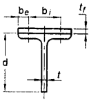
Figure description:
- Subject: Cross-section diagram of a structural T-beam.
- Key Dimensions:
- d: Total depth of the section.
- t: Thickness of the vertical web.
- : Thickness of the horizontal flange.
- : Width of the flange overhang.
- : Inner width dimension across the flange.
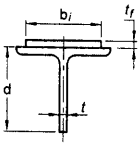
Figure description:
The image is a technical cross-section diagram of a structural T-beam with an additional top plate. Key labeled dimensions include:
- : Width of the top rectangular plate.
- : Thickness of the top rectangular plate.
- : Overall depth from the bottom of the stem to the top of the T-section flange.
- : Thickness of the vertical stem.
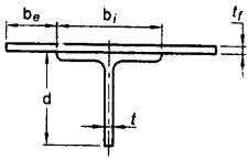
Figure description:
Compound Element Diagram Key Details:
- Subject: Cross-sectional technical drawing of a T-section structural member joined to a flat plate.
- Dimensional Labels:
- : Width of the plate overhang.
- : Width of the internal plate section above the flange.
- : Thickness of the top plate.
- : Depth of the vertical web.
- : Thickness of the vertical web.
COMPOUND ELEMENTS
Internal Element Width
— External Element Width
Fig. 2 DIMENSIONS OF SECTIONS
- a) Outstanding width of compound element (be) to its own thickness.
- b) The internal width of each added plate between the lines of welds or fasteners connecting it to the original section to its own thickness.
- c) Any outstand of the added plates beyond the line of welds or fasteners connecting it to original section to its own thickness.