10.5.1 General
Requirements of welds and welding shall conform to IS 816 and IS 9595, as appropriate.
10.5.1.1 End returns
Fillet welds terminating at the ends or sides of parts should be returned continuously around the corners for a distance of not less than twice the size of the weld, unless it is impractical to do so. This is particularly important on the tension end of parts carrying bending loads.
10.5.1.2 Lap joint
In the case of lap joints, the minimum lap should not be less than four times the thickness of the thinner part joined or 40 mm, whichever is more. Single end fillet should be used only when lapped parts are restrained from openings. When end of an element is connected only by parallel longitudinal fillet welds, the length of the weld along either edge should not be less than the transverse spacing between longitudinal welds.
10.5.1.3
A single fillet weld should not be subjected to moment about the longitudinal axis of the weld.
10.5.2 Size of Weld
10.5.2.1
The size of normal fillets shall be taken as the minimum weld leg size. For deep penetration welds, where the depth of penetration beyond the root run is a minimum of 2.4 mm, the size of the fillet should be taken as the minimum leg size plus 2.4 mm.
10.5.2.2
For fillet welds made by semi-automatic or automatic processes, where the depth of penetration is considerably in excess of 2.4 mm, the size shall be taken considering actual depth of penetration subject to agreement between the purchaser and the contractor.
10.5.2.3
The size of fillet welds shall not be less than 3 mm. The minimum size of the first run or of a single run fillet weld shall be as given in Table 21, to avoid the risk of cracking in the absence of preheating.
10.5.2.4
The size of butt weld shall be specified by the effective throat thickness.
10.5.3 Effective Throat Thickness
10.5.3.1
The effective throat thickness of a fillet weld
shall not be less than 3 mm and shall generally not exceed 0.7t, or 1.0t under special circumstances, where is the thickness of the thinner plate of elements being welded.
Table 21 Minimum Size of First Run or of a Single Run Fillet Weld
(Clause 10.5.2.3)
| SI No. | Thickness of Thicker Part mm | Minimum Size mm | |
|---|---|---|---|
| Over | Up to and Including | ||
| (1) | (2) | (3) | (4) |
| i) | – | 10 | 3 |
| ii) | 10 | 20 | 5 |
| iii) | 20 | 32 | 6 |
| iv) | 32 | 50 | 8 of first run 10 for minimum size of weld |
Notes
NOTES 1 When the minimum size of the fillet weld given in the table is greater than the thickness of the thinner part, the minimum size of the weld should be equal to the thickness of the thinner part. The thicker part shall be adequately preheated to prevent cracking of the weld.
cracking of the weld. 2 Where the thicker part is more than 50 mm thick, special
2 Where the thicker part is more than 50 mm thick, special precautions like pre-heating should be taken.
10.5.3.2
For the purpose of stress calculation in fillet welds joining faces inclined to each other, the effective throat thickness shall be taken as times the fillet size, where is a constant, depending upon the angle between fusion faces, as given in Table 22.
10.5.3.3
The effective throat thickness of a complete penetration butt weld shall be taken as the thickness of the thinner part joined, and that of an incomplete penetration butt weld shall be taken as the minimum thickness of the weld metal common to the parts joined, excluding reinforcements.
10.5.4 Effective Length or Area of Weld
10.5.4.1
The effective length of fillet weld shall be taken as only that length which is of the specified size and required throat thickness. In practice the actual length of weld is made of the effective length shown in drawing plus two times the weld size, but not less than four times the size of the weld.
10.5.4.2
The effective length of butt weld shall be taken as the length of the continuous full size weld, but not less than four times the size of the weld.
Table 22 Values of K for Different Angles Between Fusion Faces
(Clause 10.5.3.2)
| Angle Between Fusion Faces | 60°-90° | 91°-100° | 101°-106° | 107°-113° | 114°-120° |
|---|---|---|---|---|---|
| Constant, K | 0.70 | 0.65 | 0.60 | 0.55 | 0.50 |
10.5.4.3
The effective area of a plug weld shall be considered as the nominal area of the hole in the plane of the faying surface. These welds shall not be designed to carry stresses.
10.5.4.4
If the maximum length of the side welds transferring shear along its length exceeds 150 times the throat size of the weld, , the reduction in weld strength as per the long joint (see 10.5.7.3) should be considered. For flange to web connection, where the welds are loaded for the full length, the above limitation would not apply.
10.5.5 Intermittent Welds
10.5.5.1
Unless otherwise specified, the intermittent
fillet welding shall have an effective length of not less than four times the weld size, with a minimum of 40 mm.
10.5.5.2
The clear spacing between the effective lengths of intermittent fillet weld shall not exceed 12 and 16 times the thickness of thinner plate joined, for compression and tension joint respectively, and in no case be more than 200 mm.
10.5.5.3
Unless otherwise specified, the intermittent butt weld shall have an effective length of not less than four times the weld size and the longitudinal space between the effective length of welds shall not be more than 16 times the thickness of the thinner part joined. The intermittent welds shall not be used in positions subject to dynamic, repetitive and alternating stresses.
10.5.6 Weld Types and Quality
For the purpose of this code, weld shall be fillet, butt, slot or plug or compound welds. Welding electrodes shall conform to IS 814.
10.5.7 Design Stresses in Welds
10.5.7.1 Shop welds
10.5.7.1.1 Fillet welds
Design strength of a fillet weld, shall be based on its throat area and shall be given by:
where
,
= partial safety factor (see Table 5).
10.5.7.1.2 Butt welds
Butt welds shall be treated as parent metal with a thickness equal to the throat thickness, and the stresses shall not exceed those permitted in the parent metal.
10.5.7.1.3 Slot or plug welds
The design shear stress on slot or plug welds shall be as per 10.5.7.1.1.
10.5.7.2 Site welds
The design strength in shear and tension for site welds made during erection of structural members shall be calculated according to 10.5.7.1 but using a partial safety factor of 1.5 .
10.5.7.3 Long joints
When the length of the welded joint, of a splice or end connection in a compression or tension element is greater than , the design capacity of weld (see 10.5.7.1.1), shall be reduced by the factor
where
throat size of the weld
10.5.8 Fillet Weld Applied to the Edge of a Plate or Section
10.5.8.1
Where a fillet weld is applied to the square edge of a part, the specified size of the weld should generally be at least 1.5 mm less than the edge thickness in order to avoid washing down of the exposed arris (see Fig. 17A).
10.5.8.2
Where the fillet weld is applied to the rounded toe of a rolled section, the specified size of the weld should generally not exceed 3/4 of the thickness of the section at the toe (see Fig. 17B).
10.5.8.3
Where the size specified for a fillet weld is such that the parent metal will not project beyond the weld, no melting of the outer cover or covers shall be allowed to occur to such an extent as to reduce the throat thickness (see Fig. 18).
10.5.8.4
When fillet welds are applied to the edges of a plate, or section in members subject to dynamic loading, the fillet weld shall be of full size with its leg length equal to the thickness of the plate or section, with the limitations specified in 10.5.8.3.
10.5.8.5
End fillet weld, normal to the direction of force shall be of unequal size with a throat thickness not less than 0.5t, where is the thickness of the part, as shown in Fig. 19. The difference in thickness of the welds shall be negotiated at a uniform slope.
10.5.9 Stresses Due to Individual Forces
When subjected to either compressive or tensile or
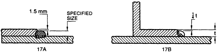
Figure description:
FIG. 17 FILLET WELDS ON SQUARE EDGE OF PLATE OR ROUND TOE OF ROLLED SECTION
-
17A: Fillet Weld on Square Edge
- Configuration: A fillet weld applied to the square edge of an overlapping plate.
- Dimensioning: The specified weld size is set 1.5 mm below the top edge of the plate.
-
17B: Fillet Weld on Round Toe of Rolled Section
- Configuration: A fillet weld applied to the rounded toe of a rolled section (e.g., an angle on a base plate.
- Dimensioning: The weld height is set at a distance of 1/4 the plate thickness ( from the top of the toe.
FIG. 17 FILLET WELDS ON SQUARE EDGE OF PLATE OR ROUND TOE OF ROLLED SECTION

Figure description:
Key Information:
- Subject: Technical diagrams showing fillet weld profiles on the square edge of a plate.
- Entities:
- Top Plate: Shown with a square vertical edge.
- Base Plate: Horizontal surface upon which the top plate rests.
- Fillet Welds: Three variations of weld bead shapes (convex to flat connecting the top plate's edge to the base plate.
- Context: Illustrates "Desirable" weld configurations for square-edged plates or round-toed rolled sections according to technical standards (Fig. 17/18A.
18A Desirable
18B Acceptable because of Full Throat Thickness
18C Not Acceptable because of Reduced Throat Thickness
FIG. 18 FULL SIZE FILLET WELD APPLIED TO THE EDGE OF A PLATE OR SECTION
shear force alone, the stress in the weld is given by:
- or
where
- shear stress, in
- effective length of weld, in mm.
10.5.10 Combination of Stresses
10.5.10.1 Fillet welds
10.5.10.1.1
When subjected to a combination of normal and shear stress, the equivalent stress shall satisfy the following:
where
10.5.10.1.2
Check for the combination of stresses need
not be done for:
- a) side fillet welds joining cover plates and flange plates, and
- b) fillet welds where sum of normal and shear stresses does not exceed (see 10.5.7.1.1).
10.5.10.2 Butt welds
10.5.10.2.1
Check for the combination of stresses in butt welds need not be carried out provided that:
- a) butt welds are axially loaded, and
- b) in single and double bevel welds the sum of normal and shear stresses does not exceed the design normal stress, and the shear stress does not exceed 50 percent of the design shear stress.
10.5.10.2.2 Combined bearing, bending and shear
Where bearing stress, is combined with bending (tensile or compressive), and shear stresses, under the most unfavorable conditions of loading in butt welds, the equivalent stress, as obtained from the following formula, shall not exceed the values allowed for the parent metal:
where
- stress
- calculated stress due to bending, in
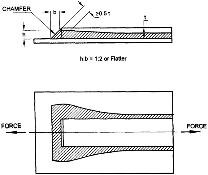
Figure description:
Subject: End fillet weld normal to the direction of force.
Key Dimensions and Constraints:
- h:b ratio: 1:2 or flatter.
- Throat thickness: 0.5 t (where t is the plate thickness.
- Chamfer: Indicated at the weld edge.
Diagram Details:
- Side View: Shows the vertical weld height (, horizontal weld width (, and plate thickness (.
- Top View: Illustrates the shaded weld area applied to a tapered component, with opposing force arrows acting perpendicular to the end weld.
FIG. 19 END FILLET WELD NORMAL TO DIRECTION OR FORCE
10.5.11
Where a packing is welded between two members and is less than 6 mm thick, or is too thin to allow provision of adequate welds or to prevent buckling, the packing shall be trimmed flush with the edges of the element subject to the design action and the size of the welds along the edges shall be increased over the required size by an amount equal to the thickness of the packing. Otherwise, the packing shall extend beyond the edges and shall be fillet welded to the pieces between which it is fitted.