7.5.1 Single Angle Struts
The compression in single angles may be transferred either concentrically to its centroid through end gusset or eccentrically by connecting one of its legs to a gusset or adjacent member.
7.5.1.1 Concentric loading
When a single angle is concentrically loaded in compression, the design strength may be evaluated using 7.1.2.
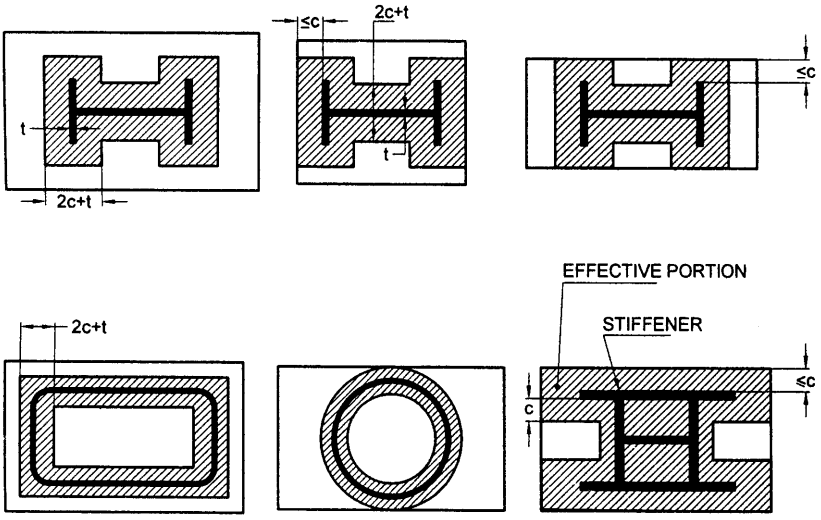
Figure description:
FIG. 9 EFFECTIVE AREA OF A BASE PLATE
- Key Entities: Structural sections (I-sections, rectangular hollow sections, circular hollow sections, base plates, and stiffeners.
- Effective Area: Represented by hatched (shaded regions surrounding the profile of the structural members.
- Parameters:
- : The outstand or distance defining the effective boundary.
- : Thickness of the structural section wall or flange.
- : Calculated width of the effective portion along specific section elements.
- Configurations:
- I-sections: Shows effective areas for standard, edge-restricted, and stiffened base plates.
- Hollow sections: Illustrates effective areas following the perimeter of rectangular and circular profiles.
- Stiffeners: Diagram demonstrates how internal stiffeners expand the effective portion of the base plate.
FIG. 9 EFFECTIVE AREA OF A BASE PLATE
7.5.1.2 Loaded through one leg
The flexural torsional buckling strength of single angle loaded in compression through one of its legs may be evaluated using the equivalent slenderness ratio, , as given below:
where
constants depending upon the end condition, as given in Table 12,
and
where
centre-to-centre length of the supportin member,
= radius of gyration about the minor axis,
width of the two legs of the angle
yield stress ratio .
| Sl No. | No. of Bolts at Each End Connection | Gusset/Connecting Member Fixity 1) | k1 | k2 | k3 | |
|---|---|---|---|---|---|---|
| (4) | (5) | (6) | ||||
| i) | Fixed | { | 0.20 | 0.35 | 20 | |
| ≥2 | Hinged | 0.70 | 0.60 | 5 | ||
| ii) | Fixed | { | 0.75 | 0.35 | 20 | |
| 1 | Hinged | 1.25 | 0.50 | 60 |
" Stiffness of in-plane rotational restraint provided by the gusset/connecting member.
For partial restraint, the can be interpolated between the results for fixed and hinged cases.
7.5.2 Double Angle Struts
7.5.2.1
For double angle discontinuous struts, connected back to back, on opposite sides of the gusset or a section, by not less than two bolts or rivets in line along the angles at each end, or by the equivalent in welding, the load may be regarded as applied axially. The effective length, , in the plane of end gusset shall be taken as between 0.7 and 0.85 times the distance between intersections, depending on the degree of the restraint provided. The effective length, , in the plane perpendicular to that of the end gusset, shall be taken as equal to the distance between centres of intersections. The calculated average compressive
stress shall not exceed the values based on 7.1.2. The angles shall be connected together over their lengths so as to satisfy the requirements of 7.8 and 10.2.5.
7.5.2.2
Double angle discontinuous struts connected back-to-back, to one side of a gusset or section by one or more bolts or rivets in each angle, or by the equivalent in welding, shall be designed in accordance with 7.5.1 and the angles shall be connected together over their lengths so as to satisfy the requirements of 7.8 and 10.2.5.
7.5.3 Continuous Members
Double angle continuous struts such as those forming the flanges, chords or ties of trusses or trussed girders, or the legs of towers shall be designed as axially loaded compression members, and the effective length shall be taken in accordance with 7.2.4.
7.5.4 Combined Stresses
In addition to axial loads, if the struts carry loads which cause transverse bending, the combined bending and axial stresses shall be checked in accordance with 9.3. For determining the permissible axial and bending stresses, the effective length shall be taken in accordance with the 7.2 and 8.3.