6.3Design Strength Due to Rupture of Critical Section
IS 800:2007, General Construction in Steel — Code of Practice
Last Updated 29 Oct 2026
Hover any section to copy its link or text, ask Copilot about it, or bookmark it.
6.3.1 Plates
The design strength in tension of a plate, Tdn, as governed by rupture of net cross-sectional area, An, at the holes is given by
Tdn=0.9Anfu/γml
where
γml= partial safety factor for failure at ultimate stress (see Table 5),
fu= ultimate stress of the material, and
An= net effective area of the member given by,
An=[b−ndh+∑i4giPsi2]t
where
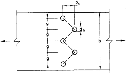
b,t= width and thickness of the plate respectively,
dh= diameter of the bolt hole ( 2mm in addition to the diameter of the hole, in case the directly punched holes),
g = gauge length between the bolt holes, as shown in Fig. 5,
ps= staggered-pitch length between line of bolt holes, as shown in Fig. 5,
n= number of bolt holes in the critical section and
i= subscript for summation of all the inclinee ’legs.
Figure description:
This image is a technical diagram illustrating a metal plate with staggered bolt holes under tension.
Key Entities and Dimensions:
Plate: A rectangular plate subjected to a tensile force, indicated by arrows on either end.
Bolt Holes: Five circular holes arranged in a staggered or zigzag pattern.
b: Represents the total width of the plate.
d_h: Represents the diameter of a bolt hole.
g: Represents the gauge, which is the transverse distance between the centerlines of bolt holes.
p_s: Represents the staggered pitch, which is the longitudinal distance between the centerlines of adjacent staggered holes.
Dashed Line: Indicates a potential net section fracture path through the staggered holes.
FIG. 5 PLATES WITH BOLTS HOLES IN TENSION
6.3.2 Threaded Rods
The design strength of threaded rods in tension, Tdn, as governed by rupture is given by
Tdn=0.9Anfu/γml
where
An= net root area at the threaded section
6.3.3 Single Angles
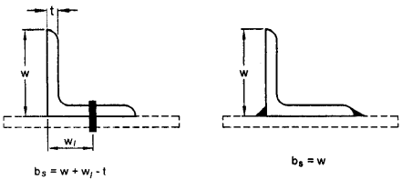
The rupture strength of an angle connected through one leg is affected by shear lag. The design strength, Tdn, as governed by rupture at net section is given by:
Lc= length of the end connection, that is the distance between the outermost bolts in the end joint measured along the load direction or length of the weld along the load direction.
For preliminary sizing, the rupture strength of net section may be approximately taken as:
Tdn=αAnfu/γml
where
α = 0.6 for one or two bolts, 0.7 for three bolts and 0.8 for four or more bolts along the length in the end connection or equivalent weld length;
An= net area of the total cross-section;
Anc= net area of the connected leg;
Agot= gross area of the outstanding leg; and = thickness of the leg.
Figure description:
FIG. 6 ANGLES WITH SINGLE LEG CONNECTIONS
Entities and Variables:
Angle: L-shaped structural member with leg width (w and thickness (t.
Connection types: Fastener (left and Welds (right.
w: Vertical leg height.
t: Material thickness.
wl: Distance from the outside corner to the fastener centerline.
bs: Calculated effective width.
Formulas for bs:
Bolted Connection:bs=w+wl−t
Welded Connection:bs=w
Fig. 6 ANGLES WITH SINGLE LEG CONNECTIONS
6.3.4 Other Section
The rupture strength, Tdn, of the double angles, channels, I-sections and other rolled steel sections, connected by one or more elements to an end gusset is also governed by shear lag effects. The design tensile strength of such sections as governed by tearing of net section may also be calculated using equation in 6.3.3, where β is calculated based on the shear lag distance, bs, taken from the farthest edge of the outstanding leg to the nearest bolt/weld line in the connected leg of the cross-section.