In the absence of a more exact analysis, the effective length of columns in framed structures may be obtained by multiplying the actual length of the column between the centres of laterally supporting members (beams) given in Fig. 27 and Fig. 28 with the effective length factor , calculated by using the equations given below, provided the connection between beam and column is rigid type:
- a) Non-sway Fmmes (BracedFrame) [(see 4.12(a)] A frame is designated as non-sway frame if the relative displacement between the two adjacent floors is restrained by bracings or shear walls (see 4.1.2). The effective length factor, K, of column in non-sway frames is given by (see Fig. 27):
- b) Sway Frames (Moment Resisting Frames) [see 4.1.2(b)]
The effective length factor , of column in sway frames is given by (see Fig. 28):
where
are given,
- effective flexural stiffness of the columns and beams meeting at the joint at the ends of the columns and rigidly connected at the joints, and these are calculated by:
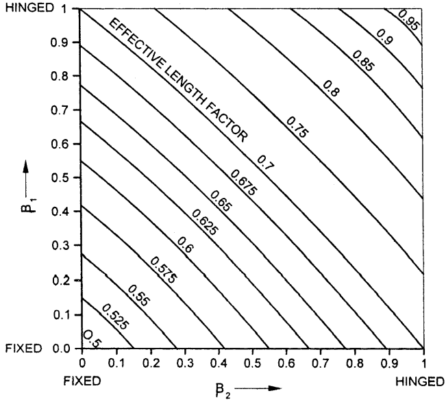
Figure description:
EFFECTIVE LENGTH FACTOR
Effective Length Factor Nomogram
Annotations
- EFFECTIVE LENGTH FACTOR (text_label - position: centered within the chart area)
- FIXED (beta_1 = 0 (text_label - position: y = 0))
- HINGED (beta_1 = 1 (text_label - position: y = 1))
- FIXED (beta_2 = 0 (text_label - position: x = 0))
- HINGED (beta_2 = 1 (text_label - position: x = 1))
| Effective Length Factor | beta_1 | beta_2 |
|---|---|---|
| 0.5 | 0.00 | 0.00 |
| 0.525 | 0.15 | 0.00 |
| 0.525 | 0.00 | 0.15 |
| 0.55 | 0.28 | 0.00 |
| 0.55 | 0.00 | 0.28 |
| 0.575 | 0.42 | 0.00 |
| 0.575 | 0.00 | 0.42 |
| 0.6 | 0.58 | 0.00 |
| 0.6 | 0.00 | 0.58 |
| 0.625 | 0.75 | 0.00 |
| 0.625 | 0.00 | 0.75 |
| 0.65 | 0.95 | 0.00 |
| 0.65 | 0.00 | 0.95 |
| 0.675 | 1.00 | 0.04 |
| 0.675 | 0.04 | 1.00 |
| 0.7 | 1.00 | 0.13 |
| 0.7 | 0.13 | 1.00 |
| 0.75 | 1.00 | 0.28 |
| 0.75 | 0.28 | 1.00 |
| 0.8 | 1.00 | 0.43 |
| 0.8 | 0.43 | 1.00 |
| 0.85 | 1.00 | 0.59 |
| 0.85 | 0.58 | 1.00 |
| 0.9 | 1.00 | 0.76 |
| 0.9 | 0.76 | 1.00 |
| 0.95 | 1.00 | 0.92 |
| 0.95 | 0.92 | 1.00 |
| 1.0 | 1.00 | 1.00 |
Notes: The chart is a nomogram used to determine the Effective Length Factor based on the end restraint parameters beta_1 and beta_2. Values range from 0 (FIXED to 1 (HINGED for both axes. The contour lines represent constant effective length factors.))
FIG. 27 COLUMN EFFECTIVE LENGTH FACTOR — NON-SWAY FRAME
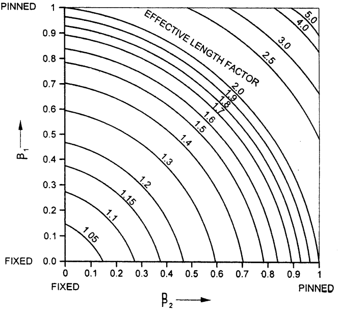
Figure description:
PINNED 1 5.0 4.0 0.9 3.0 EFFECTIVE LENGTH FACTOR 0.8- 2.5
0.7
0.6 1.6 1.5 0.5- 1.4 B₁ 0.4- 1.3
0.3 1.2 1.15 0.2- 1.1
0.1- 1.05
FIXED 0.0 0 0.1 0.2 0.3 0.4 0.5 0.6 0.7 0.8 0.9 1 FIXED PINNED P₂
FIG. 28 COLUMN EFFECTIVE LENGTH FACTOR — SWAY FRAME
- = moment of inertia of the member about an axis perpendicular to the plan of the frame.
- = correction factor as shown in Table 35.
| Sl No. (1) | Far End Condition (2) | Correction Factor, C | |
|---|---|---|---|
| Braced Frame (3) | Unbraced Frame (4) | ||
| i) | Pinned | 1.5(1 − n̄) | 1.5(1 − n̄) |
| ii) | Rigidly connected to column | 1.0(1 − n̄) | 1.0(1 − 0.2n̄) |
| iii) | Fixed | 2.0(1 − 0.4n̄) | 0.67(1 − 0.4n̄) |
| NOTE — n̄ = P / Pc | |||
| where | |||
| Pe = elastic buckling load, and | |||
| P = applied load. | |||