The design bending strength of beam, adequately supported against lateral torsional buckling (laterally supported beam) is governed by the yield stress (see 8.2.1). When a beam is not adequately supported against lateral buckling (laterally un-supported beams) the design bending strength may be governed by lateral torsional buckling strength (see 8.2.2).
The factored design moment, at any section, in a beam due to external actions, shall satisfy
where
8.2.1 Laterally Supported Beam
A beam may be assumed to be adequately supported at the supports, provided the compression flange has full lateral restraint and nominal torsional restraint at supports supplied by web cleats, partial depth end plates, fin plates or continuity with the adjacent span. Full lateral restraint to compression flange may be
assumed to exist if the frictional or other positive restraint of a floor connection to the compression flange of the member is capable of resisting a lateral force not less than 2.5 percent of the maximum force in the compression flange of the member. This may be considered to be uniformly distributed along the flange, provided gravity loads constitute the dominant loading on the member and the floor construction is capable of resisting this lateral force.
The design bending strength of a section which is not susceptible to web buckling under shear before yielding (where ) shall be determined according to 8.2.1.2.
8.2.1.1
Section with webs susceptible to shear buckling before yielding
When the flanges are plastic, compact or semi-compact but the web is susceptible to shear buckling before yielding (d/tw ≤ 67€), the design bending strength shall be calculated using one of the following methods:
- a) The bending moment and axial force acting on the section may be assumed to be resisted by flanges only and the web is designed only to resist shear (see 8.4).
- b) The bending moment and axial force acting on the section may be assumed to be resisted by the whole section. In such a case, the web shall be designed for combined shear and normal stresses using simple elastic theory in case of semi-compact webs and simple plastic theory in the case of compact and plastic webs.
8.2.1.2
When the factored design shear force does not exceed , where is the design shear strength of the cross-section (see 8.4), the design bending strength, shall be taken as:
To avoid irreversible deformation under serviceability loads, shall be less than incase of simply supported and in cantilever beams; where
for plastic and compact sections
for semi-compact sections;
plastic and elastic section modulli of the cross-section, respectively;
= yield stress of the material; and
8.2.1.3
When the design shear force (factored), exceeds , where is the design shear strength of the cross-section (see 8.4) the design bending strength, shall be taken
partial safety factor (see 5.4.1).
where
design bending strength under high shear as defined in 9.2.
8.2.1.4 Holes in the tension zone
- a) The effect of holes in the tension flange, on the design bending strength need not be considered if
where
- ratio of net to gross area of the flange in tension,
When the does not satisfy the above requirement, the reduced effective flange area satisfying the above equation may be taken as the effective flange area in tension, instead of .
- b) The effect of holes in the tension region of the web on the design flexural strength need not be considered, if the limit given in (a) above is satisfied for the complete tension zone of the cross-section, comprising the tension flange and tension region of the web.
- c) Fastener holes in the compression zone of the cross-section need not be considered in design bending strength calculation, except for oversize and slotted holes or holes without any fastener.
8.2.1.5 Shear lag effects
The shear lag effects in flanges may be disregarded provided:
- a) For outstand elements (supported along one edge), ; and
- b) For internal elements (supported along two edges), .
where
- width of the flange with outstand, and
Where these limits are exceeded, the effective width of flange for design strength may be calculated using
specialist literature, or conservatively taken as the value satisfying the limit given above.
8.2.2 Laterally Unsupported Beams
Resistance to lateral torsional buckling need not be checked separately (member may be treated as laterally supported, see 8.2.1) in the following cases:
- a) Bending is about the minor axis of the section,
- b) Section is hollow (rectangular/ tubular) or solid bars, and
- c) In case of major axis bending, (as defined herein) is less than 0.4.
The design bending strength of laterally unsupported beam as governed by lateral torsional buckling is given by:
where
- for plastic and compact sections
for semi-compact sections.
- plastic section modulus and elastic section modulus with respect to extreme compression fibre.
, the imperfection parameter is given by:
for rolled steel section
for welded steel section
The non-dimensional slenderness ratio, , is given by
where
extreme fibre bending compressive stress
corresponding to elastic lateral bucklin moment (see 8.2.2.1 and Table 14).
8.2.2.1 Elastic lateral torsional buckling moment
In case of simply supported, prismatic members with symmetric cross-section, the elastic lateral buckling moment, , can be determined from:
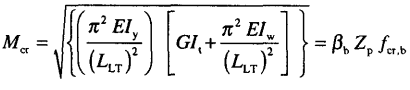
Figure description:
The image contains a mathematical formula for the elastic lateral buckling moment (:
Key Entities:
- : Elastic lateral buckling moment.
- : Modulus of elasticity.
- : Moment of inertia about the minor axis.
- : Effective length for lateral-torsional buckling.
- : Shear modulus.
- : Torsional constant.
- : Warping constant.
- : A coefficient related to section properties.
- : Plastic section modulus.
- : Critical buckling stress.
of non-slender rolled steel sections in the above equation may be approximately calculated from the values given in Table 14, which has been prepared using the following equation:
The following simplified equation may be used in the case of prismatic members made of standard rolled I-sections and welded doubly symmetric I-sections, for calculating the elastic lateral buckling moment, (see Table 14):
where
warping constant
- centre-to-centre distance between flanges; and
thickness of the flange.
for different beam sections, considering loading, support condition, and non-symmetric section, shall be more accurately calculated using the method given in Annex E.