2.3.1
Rivets shall be manufactured from steel
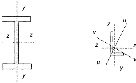
Figure description:
The image depicts technical diagrams of two structural steel cross-sections with labeled axes of symmetry and rotation.
Left Diagram: I-Beam (Universal Beam
- y-y axis: Vertical axis of symmetry passing through the center of the web.
- z-z axis: Horizontal axis of symmetry passing through the center of the web's height.
Right Diagram: L-Beam (Angle Section
- y-y axis: Vertical axis passing through the vertical leg.
- z-z axis: Horizontal axis passing through the horizontal leg.
- u-u axis: Principal axis oriented diagonally.
- v-v axis: Principal axis oriented perpendicular to the u-u axis.
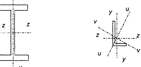
Figure description:
Key Information:
Entities and Axes:
- I-beam (Left:
- y-axis: Vertical centroidal axis.
- z-axis: Horizontal centroidal axis.
- Angle section (Right:
- y-axis: Vertical centroidal axis.
- z-axis: Horizontal centroidal axis.
- u-axis: Principal major axis.
- v-axis: Principal minor axis.
Fig. 1 Axes of MEMBERS
Table 1 Tensile Properties of Structural Steel Products
(Clauses 1.3.113, 1.3.119 and 2.2.4.2)
| SI No. | Indian Standard | Grade/ Classification | Properties | |||||||||
|---|---|---|---|---|---|---|---|---|---|---|---|---|
| Yield Stress MPa, Min | Ultimate Tensile Stress MPa, Min | Elongation, Percent, Min | ||||||||||
| (1) | (2) | (3) | (4) | (5) | (6) | |||||||
| O | --- | |||||||||||
| i) | IS 513 | D | 280 | 270-410 | 28 | |||||||
| DD | 250 | 270-370 | 32 | |||||||||
| EDD | 220 | 270-350 | 35 | |||||||||
| Ex40xx | 330 | 410-540 | 16 | |||||||||
| ii) | IS 814 | Ex41xx | 330 | 410-540 | 20 | |||||||
| Ex42xx | 330 | 410-540 | 22 | |||||||||
| Ex43xx | 330 | 410-540 | 24 | |||||||||
| Ex44xx | 330 | 410-540 | 24 | |||||||||
| Ex50xx | 360 | 510-610 | 16 | |||||||||
| Ex51xx | 360 | 510-610 | 18 | |||||||||
| Ex52xx | 360 | 510-610 | 18 | |||||||||
| Ex53xx | 360 | 510-610 | 20 | |||||||||
| Ex54xx | 360 | 510-610 | 20 | |||||||||
| Ex55xx | 360 | 510-610 | 20 | |||||||||
| Ex56xx | 360 | 510-610 | 20 | |||||||||
| iii) | IS 1079 | O | --- | |||||||||
| D | --- | 240-400 | 25 | |||||||||
| DD | --- | 260-390 | 28 | |||||||||
| EDD | --- | 260-380 | 32 | |||||||||
| 3.6 | 330 | 25 | ||||||||||
| 4.6 | 400 | 22 | ||||||||||
| 4.8 | 420 | 20 | ||||||||||
| 5.6 | 500 | --- | ||||||||||
| 5.8 | 520 | --- | ||||||||||
| 6.8 | 600 | --- | ||||||||||
| iv) | IS 1367 (Part 3) | 8.8 (d≤ 16 mm) | 6401) | 800 | 12 | |||||||
| 8.8 (d> 16 mm) | 6601) | 830 | 12 | |||||||||
| 9.8 | 7201) | 900 | 10 | |||||||||
| 10.9 | 9401) | 1 040 | 9 | |||||||||
| 12.9 | 1 1001) | 1 220 | 8 | |||||||||
| v) | IS 1875 | 1 | 200 | 370 | 26 | |||||||
| 1A | 220 | 410 | 25 | |||||||||
| 2 | 230 | 430 | 24 | |||||||||
| 2A | 250 | 460 | 22 | |||||||||
| 3 | 270 | 490 | 21 | |||||||||
| 3A | 280 | 540 | 20 | |||||||||
| 4 | 320 | 620 | 15 | |||||||||
| 5 | 350 | 710 | 13 | |||||||||
| 6 | 370 | 740 | 10 | |||||||||
| d or t | ||||||||||||
| ≤ 20 | > 20 | |||||||||||
| vi) | IS 1990 | S,37 | 220 | 200 | 360-440 | 26 | ||||||
| S,42 | 250 | 240 | 410-500 | 23 | ||||||||
| t | t | t | ||||||||||
| ≤ 16 | > 16 and ≤ 40 | > 40 and ≤ 60 | > 60 and ≤ 100 | > 100 and ≤ 350 | ≤ 60 | > 60 and ≤ 100 | > 100 and ≤ 350 | ≤ 60 | > 60 | |||
| vii) | IS 2002 | 1 | 235 | 225 | 215 | 200 | 185 | 360-480 | 360-480 | 350-480 | 24 | 23 |
| 2 | 265 | 255 | 245 | 215 | 200 | 410-530 | 410-530 | 400-530 | 22 | 21 | ||
| 3 | 290 | 285 | 280 | 255 | 230 | 460-580 | 450-570 | 440-570 | 21 | 20 | ||
| SI No. | Indian Standard | Grade/Classification | Properties | ||||
|---|---|---|---|---|---|---|---|
| Yield Stress MPa, Min | Ultimate Tensile Stress MPa, Min | Elongation, Percent, Min | |||||
| (3) | (4) | (5) | (6) | ||||
| d or t | |||||||
| < 20 | 20-40 | > 40 | |||||
| viii) | IS 2062 | E 165 (Fe 290) | 165 | 165 | 165 | 290 | 23 |
| E 250 (Fe 410 W) A | 250 | 240 | 230 | 410 | 23 | ||
| E 250 (Fe 410 W) B | 250 | 240 | 230 | 410 | 23 | ||
| E 250 (Fe 410 W) C | 250 | 240 | 230 | 410 | 23 | ||
| E 300 (Fe 440) | 300 | 290 | 280 | 440 | 22 | ||
| E 350 (Fe 490) | 350 | 330 | 320 | 490 | 22 | ||
| E 410 (Fe 540) | 410 | 390 | 380 | 540 | 20 | ||
| E 450 (Fe 570) D | 450 | 430 | 420 | 570 | 20 | ||
| E 450 (Fe 590) E | 450 | 430 | 420 | 590 | 20 | ||
| d or t | |||||||
| ≤25 | > 25 and ≤ 50 | ||||||
| ix) | IS 3039 | I | 230 | 220 | 400-490 | 22 | |
| II | 235 | 235 | 400-490 | 22 | |||
| III | 235 | 235 | 400-490 | 22 | |||
| x) | IS 6240 | Grade 1 | 240 | 350-450 | 25 | ||
| Grade 2 | 245 | 360-450 | 34 | ||||
| xi) | IS 7557 | Annealed Condition | 160 | 330-410 | 30 | ||
| As-Drawn Condition | 190 | 410-490 | 20 | ||||
| xii) | IS 9295 | HFC 210/CDS 210/ERW210 | 210 | 330 | 20 | ||
| HFC 240/CDS 240/ERW240 | 240 | 410 | 18 | ||||
| HFC 310/CDS 310/ERW310 | 310 | 450 | 15 | ||||
| xiii) | IS 10748 | 1 | 170 | 290 | 30 | ||
| 2 | 210 | 330 | 28 | ||||
| 3 | 240 | 410 | 25 | ||||
| 4 | 275 | 430 | 20 | ||||
| 5 | 310 | 490 | 15 | ||||
NOTES
- 1 Percent of elongation shall be taken over the gauge length , where Original cross-sectional area of the test specimen.
- 2 Abbreviations: O = Ordinary, D = Drawing, DD = Deep Drawing, EDD = Extra Deep Drawing.
- Stress at 0.2 percent non-proportional elongation, Min.
conforming to IS 7557. They may also be manufactured from steel conforming to IS 2062 provided that the steel meets the requirements given in IS 1148.
2.3.2
Rivets shall conform to IS 1929 and IS 2155 as appropriate.
2.3.3 High Tensile Steel Rivets
High tensile steel rivets, shall be manufactured from steel conforming to IS 1149.