TO IS 800 : 2007 GENERAL CONSTRUCTION IN STEEL — CODE OF PRACTICE
(Third Revision)
[(Page (iii), Section 17] — Insert the following new item, as appropriate:
17.15 Bedding Requirement 116'
(Page 6, line 38) — Delete the symbols ‘Cmy, Cmz’ and the corresponding explanation.
(Page 8, line 33) — Insert the following symbols and explanations after this line:
— Moment amplification factors (see 4.4.2, 4.4.3.1, 4.4.3.3 and 9.3.2.2)'
(Page 18, Table 2, col 2) — Substitute ‘d/t’ for ‘D/tf’ for entry against ‘Stem of a T-section, rolled or cut from a rolled I- or H-section’.
(Page 18, Table 2, col 3, 4 and 5) — Substitute ‘but ≥ 42ε’ for ‘but ≤ 42 ε’ for entries against ‘Web of an I, H or box section’.
(Page 18, Table 2, Notes, last line) — Substitute ‘overall’ for ‘overll’.
(Page 19, Fig. 2, ROLLED CHANNELS) — Substitute ‘d’ for ‘h’ in the figure.
(Page 24, clause 4.4.2, line 10) — Substitute ‘Ky, Kz’ for ‘Cy, Cz’.
(Page 24, clause 4.4.3.1, line 9) — Substitute ‘Ky and Kz’ for ‘Cy and Cz’.
(Page 24, clause 4.4.3.3, line 3) — Substitute ‘(Ky, Kz)’ for ‘(Cmy, Cmz)’.
(Page 25, clause 4.5.2, line 19) — Insert ‘less’ between ‘be’ and ‘than’.
(Page 31, clause 5.6.1, line 6) — Substitute ‘using load factors of Table 4.’ for ‘using a load factor of 1.0.’
(Page 31, clause 5.6.1, third sentence) — Insert the following at the end:
'In Table 6, live load should include all post construction loads including superimposed dead loads.'
(Page 33, clause 6.3.3, line 6) — Substitute ‘0.9 fu γm0/fy γml’ for ‘fu γm0/fy γml’.
(Page 34, clause 7.1.2, line 1) — Substitute the following for the existing:
The factored design compression, in members shall satisfy the following requirement:
(Page 34, clause 7.1.2.1, line 20) — Substitute ‘γmo’ for ‘λmo’.
Amend No. 1 to IS 800 : 2007
(Page 35, Fig. 8) — Insert ‘λ’ as the title of the abscissa (x-axis).
(Page 44, Table 10, col 2, line 3) — Substitute ‘40 mm < tf ≤ 100 mm’ for ‘40 ≤ mm < tf ≤ 100 mm’.
(Page 45, Table 11, second row, col 1 and 2) — Substitute the following for the existing entries:
(1) Restrained (2) Free
(Page 48, clause 7.5.1.2, line 4) — Add the following in the end:
“, in place of in 7.1.2.1 and using curve ”
(Page 48, clause 7.5.1.2, line 9, formula) — Substitute the following for the existing:
and ,
(Page 49, Fig. 10) — Substitute the following figure for the existing as appropriate, and substitute ‘Members’ for ‘Numbers’ in the sub-title of Fig. 10C and substitute the existing title of Fig. 10 with ‘Top RESTRAINT CONDITIONS’:
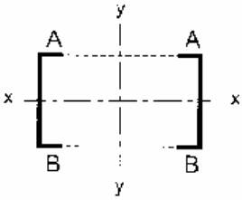
Figure description:
- Title: TOP RESTRAINT CONDITIONS (substituted for Fig. 10
- Key Entities:
- Two symmetrical C-shaped structural members facing inward.
- Axes: Horizontal x-x axis (neutral axis and vertical y-y axis of symmetry.
- Labels: Points marked 'A' at the top flanges and 'B' at the bottom flanges.
- Visual details: Dashed/dotted lines connect the top and bottom flanges across the y-axis, indicating restraint or connectivity between the members.
(Page 53, clause 8.2.1.1, line 3) — Substitute ‘ ’ for ‘ ’.
(Page 54, clause 8.3.1, second para) — Substitute the following for the existing:
'In simply supported beams with intermediate lateral restraints against lateral torsional buckling, the effective length for lateral torsional buckling, to be used in 8.2.2.1 shall be taken as the length of the relevant segment in between the lateral restraints. In the case of intermediate partial lateral restraints, the effective length, shall be taken as equal to 1.2 times the length of the relevant segment in between the partial lateral restraints.'
(Page 57, Table 14) — Substitute ‘ ’ and ‘ ’ for ‘ ’ and ‘ ’.
(Page 58, clause 8.3.2, line 9) — Insert ‘centre’ between ‘shear’ and ‘and’.
(Page 58, Table 15, col 3, first row) — Substitute ‘Both flanges partially restrained’ for ‘Both flanges fully restrained’.
Amend No. 1 to IS 800 : 2007
(Page 59, clause 8.4.2.1) — Substitute ‘εw’ for ‘ε’ and ‘fyw’ for ‘fy’, wherever appearing.
(Page 60, clause 8.4.2.2, col 1, line 18 from top) — Substitute ‘ cr,e for cr,e
(Page 60, clause 8.4.2.2, col 2, line 52) — Substitute 'nearly = tan⁻¹ (a/c)/1.5', for ' = tan⁻¹ (d/c)',
(Page 60, clause 8.4.2.2, col 2, line 55) — Substitute , for the existing.
(Page 60, clause 8.4.2.2, col 2, lines 59 and 60) — Delete the lines.
(Page 60, clause 8.5.1, line 3) — Insert ‘out’ between ‘carried’ and ‘in’.
(Page 61, Table 16, last row, col 1) — Substitute the following for the existing figure:
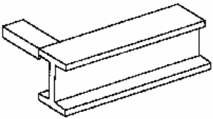
Figure description:
The image depicts a structural steel I-beam with a rectangular plate or smaller beam welded perpendicularly to its top flange. The I-beam consists of a vertical web and two horizontal flanges.
(Page 62, Fig. 12) — Substitute the following for the existing figure:
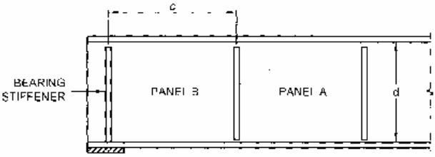
Figure description:
The image is a technical schematic of a structural beam section with vertical stiffeners and designated panels.
Key Entities and Components:
- Bearing Stiffener: The leftmost vertical structural element located over the support.
- Panel B: The first section of the web, defined by width dimension .
- Panel A: The subsequent section of the web to the right of Panel B.
- Dimension : Horizontal distance between the bearing stiffener and the first intermediate stiffener.
- Dimension : Vertical depth of the web between the top and bottom flanges.
- Support: Indicated by the hashed area beneath the bearing stiffener.
NOTES
1 Panel is designed utilizing tension field action as given in 8.4.2.2(b).
2 Panel is designed using simple post critical method as given in 8.4.2.2(a).
- 3 Bearing stiffener is designed for the compressive force due to bearing plus compressive force due to the moment as given in 8.5.3.
FIG. 12 END PANEL DESIGNED not USING TENSION FIELD ACTION
(Page 63, Fig. 13, Notes) — Delete NOTE 2 and renumber the subsequent Note accordingly.
(Page 63, clause 8.6.1.1)— Substitute ‘εw’ for ‘ε’ wherever appearing.
(Page 63, clause 8.6.1.1, line 13) — Substitute ‘c < 0.74d’ for ‘c < d’.
Amend No. 1 to IS 800 : 2007
(Page 64, clause 8.6.1.2, line 15) — Substitute ‘εf = yield stress ratio of flange = √(250/fyf), for ‘εf = yield
stress ratio of web
(Page 65, clause 8.7.1.2, second para, line 1) — Insert ‘stiffener’ between the words ‘web’ and ‘is’.
[Page 70, clause 9.3.1.2(c)] — Substitute the following for the existing:
c) For standard I or H sections
for for
(Page 72, Table 18) — Substitute the following for the existing table:
| Bending Moment Diagram (1) | Range (2) | Cmy, Cmz, CmLT | ||
|---|---|---|---|---|
| Condition on α/αh | Condition on ψ | Uniform Loading (3) | Concentrated Load (4) | |
| M ψM | -1 ≤ ψ ≤ 1 | 0.6 + 0.4 ψ ≥ 0.4 | ||
| Mh Ms αs = Ms/Mh | 0 ≤ αs ≤ 1 | -1 ≤ ψ ≤ 1 | 0.2 + 0.8 αs ≥ 0.4 | 0.2 + 0.8 αs ≥ 0.4 |
| -1 ≤ αs ≤ 0 | 0 ≤ ψ ≤ 1 | 0.1 - 0.8 αs ≥ 0.4 | -0.8 αs ≥ 0.4 | |
| -1 ≤ ψ ≤ 0 | 0.1(1-ψ) - 0.8 αs ≥ 0.4 | 0.2(-ψ) - 0.8 αs ≥ 0.4 | ||
| Mh M αh = M/Ms | 0 ≤ αh ≤ 1 | -1 ≤ ψ ≤ 1 | 0.95 - 0.05 αh | 0.90 + 0.10 αh |
| -1 ≤ αh ≤ 0 | 0 ≤ ψ ≤ 1 | 0.95 + 0.05 αh | 0.90 + 0.10 αh | |
| -1 ≤ ψ ≤ 0 | 0.95 + 0.05 αh (1+2ψ) | 0.90 + 0.1αh (1+2ψ) | ||
For members with sway buckling mode, the equivalent uniform moment factor .
| Moment factor | Bending axis | Points braced in direction |
|---|---|---|
| Cmy | z-z | y-y |
| Cmz | y-y | z-z |
| CmLT | z-z | z-z |
Amend No. 1 to IS 800 : 2007
(Page 75, clause 10.3.2, line 3) — Substitute the following for the existing:
(Page 76, clause 10.4.3, first sentence) — Substitute the following for the existing:
'Design for friction type bolting, where slip resistance is required at factored design force , shall satisfy the following:'
(Page 76, clause 10.4.3, line 14) — Substitute ‘μf ≤ 0.55’ for ‘μf = 0.55’.
(Page 76, clause 10.4.3, Note, line 1) — Substitute ‘Vnsf’ for ‘Vns’.
(Page 77, clause 10.4.5, col 1, line 6, from top, formula) — Substitute for .
(Page 80, clause 10.5.10.2.2, line 7, formula)— Substitute for .
(Page 89, clause 12.8.2.1, first sentence) — Substitute the following for the existing:
Bracing members shall be made of E250B steel of IS 2062 or of steel having Charpy V-notch energy, E > 27J.
(Page 90, clause 12.11.1, line 2) — Insert ‘or of steel having Charpy V-notch energy, E > 27J’ between ‘IS 2062’ and ‘and’.
(Page 106, clause 16.4.1, line 4, formula) — Substitute for the existing.
(Page 121, Annex B, clause B-3.2, line 10 from top, formula) — Substitute , for .
(Page 121, Annex B, clause B-3.2, lines 12, 13 and 16 from top) – Substitute ‘h’, ‘δui’ and ‘δLi’ for ‘h’, ‘δu’ and ‘δL’.
(Page 128, Annex E, clause E-1.2, line 5, formula) — Substitute ‘(LLT)²’ for ‘(LLT)’.
(Page 128, Annex E, clause E-1.2, line 30) — Substitute ‘(z² + y²)²’ for ‘(z² – y²)’.
(Page 129, Annex E, clause E-1.2, col 1, line 18 from top) — Insert ‘St. Venant’s’ before ‘torsion’.
(Page 130, Table 42, col 5, row 7) — Substitute ‘1.267’ for ‘1.257’.
(Page 129, Table 42, col 6, rows 5 and 10) — Substitute ‘1.730’ for ‘1.780’ and ‘1.890’ for ‘1.390’, respectively.
(CED 7)