8.5.1 End Panels Design (see Fig. 12)
The design of end panels in girders in which the interior panel (panel A) is designed using tension field action shall be carried in accordance with the provisions given herein. In this case the end panel should be designed
| Restraint Condition | Loading Condition | ||
|---|---|---|---|
| At Support | At Top | Normal | Destabilizing |
| (1) | (2) | (3) | (4) |
a) Continuous, with lateral restraint to top flange  | i) Free | 3.0L | 7.5L |
| ii) Lateral restraint to top flange | 2.7L | 7.5L | |
| iii) Torsional restraint | 2.4L | 4.5L | |
| iv) Lateral and torsional restraint | 2.1L | 3.6L | |
b) Continuous, with partial torsional restraint  | i) Free | 2.0L | 5.0L |
| ii) Lateral restraint to top flange | 1.8L | 5.0L | |
| iii) Torsional restraint | 1.6L | 3.0L | |
| iv) Lateral and torsional restraint | 1.4L | 2.4L | |
c) Continuous, with lateral and torsional restraint  | i) Free | 1.0L | 2.5L |
| ii) Lateral restraint to top flange | 0.9L | 2.5L | |
| iii) Torsional restraint | 0.8L | 1.5L | |
| iv) Lateral and torsional restraint | 0.7L | 1.2L | |
d) Restrained laterally, torsionally and against rotation on plan  | i) Free | 0.8L | 1.4L |
| ii) Lateral restraint to top flange | 0.7L | 1.4L | |
| iii) Torsional restraint | 0.6L | 0.6L | |
| iv) Lateral and torsional restraint | 0.5L | 0.5L | |
| Top restraint conditions | |||
i) Free | ii) Lateral restraint to top flange  | iii) Torsional restraint | iv) Lateral and torsional restraint  |
using only simple post critical method, according to 8.4.2.2(a).
Additionally, the end panel along with the stiffeners should be checked as a beam spanning between the flanges to resist a shear force, and a moment, due to tension field forces as given in 8.5.3. Further, end stiffener should be capable of resisting the reaction plus a compressive force due to the moment, equal to (see Fig. 12).
8.5.2
End Panels Designed Using Tension Field Action (see Fig. 13 and Fig. 14)
The design of end panels in girders, which are designed using tension field action shall be carried out in accordance with the provisions mentioned herein. In this case, the end panel (Panel B) shall be designed according to 8.4.2.2(b).
Additionally it should be provided with an end post consisting of a single or double stiffener (see Fig. 13 and Fig. 14), satisfying the following:
- a) Single stiffener (see Fig. 13) — The top of the end post should be rigidly connected to the flange using full strength welds. The end post should be capable of resisting the reaction plus a moment from the anchor forces equal to due to tension field forces, where is obtained from 8.5.3. The width and thickness of the end post are not to exceed the width and thickness of the flange.
- b) Double stiffener (see Fig. 14) — The end post should be checked as a beam spanning between the flanges of the girder and capable of resisting a shear force and a moment, due to the tension field forces as given in 8.5.3.
8.5.3 Anchor Forces
The resultant longitudinal shear, , and a moment from the anchor of tension field forces are evaluated as given below:
and
where
If the actual factored shear force, in the panel designed using tension field approach is less than the shear strength, as given in 8.4.2.2(b), then the values
of may be reduced by the ratio
where
8.5.4
Panels with Openings — Panels with opening of dimension greater than 10 percent of the minimum panel dimension should be designed without using tension field action as given in 8.4.2.2(b). The adjacent panels should be designed as an end panel as given in 8.5.1 or 8.5.2, as appropriate.
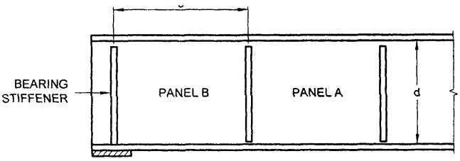
Figure description:
Key Information:
- Structural Diagram: Illustrates a beam section with vertical stiffeners and web panels.
- Key Entities:
- Bearing Stiffener: Located at the far left support end.
- Panel B: The end panel adjacent to the bearing stiffener, with horizontal width marked as c.
- Panel A: An internal panel adjacent to Panel B.
- Dimension d: Represents the vertical depth of the web between the top and bottom flanges.
NOTES
- 1 Panel is designed utilizing tension field action as given in 8.4.2.2(b).
- 2 Panel is designed without utilizing tension field action as given in 8.4.2.2(a).
- 3 Bearing stiffener is designed for the compressive force due to bearing plus compressive force due to the moment as given in 8.5.3.
FIG. 12 END PANEL DESIGNED not USING TENSION FIELD ACTION
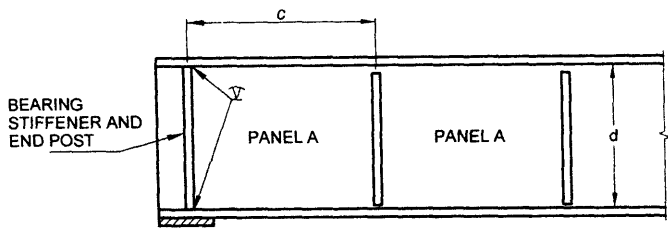
Figure description:
Key Entities and Information:
- Structural Component: A side-profile technical drawing of a beam or girder.
- Bearing Stiffener and End Post: The vertical element at the far left of the beam.
- Panel A: Labeled sections of the web between vertical stiffeners.
- Dimension c: Represents the horizontal width of a panel.
- Dimension d: Represents the vertical depth or height of the beam web.
- Stiffeners: Vertical bars spaced along the beam to provide structural reinforcement.
- Weld Symbols: Indicated at the junction points of the end post stiffener.
Notes
- 1 Panel A is designed utilizing tension field action as given in 8.4.2.2(b).
- 2 Panel B is designed utilizing tension field action as given in 8.4.2.2(b).
- 3 Bearing stiffener and end post is designed for combination of compressive loads due to bearing and a moment equal to as given in 8.5.3. FIG. 13 END PANEL DESIGNED USING TENSION FIELD ACTION (SINGLE STIFFENER)
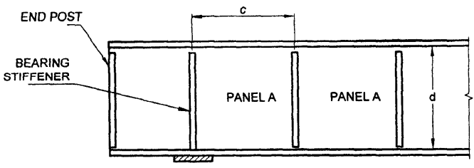
Figure description:
Key Information:
- Structure: Technical diagram of a beam or girder divided into sections.
- Entities:
- End Post: The leftmost vertical terminal component.
- Bearing Stiffener: Vertical internal reinforcement members.
- Panel A: The repeated sections of the beam between stiffeners.
- Dimensions:
- c: Horizontal distance (width between vertical stiffeners.
- d: Vertical height of the beam panels.
NOTES
- 1 Panel A is designed utilizing tension field action as given in 8.4.2.2(b).
- 2 Bearing stiffener is designed for compressive force due to bearing as given in 8.4.2.2(a).
- 3 End post is designed for horizontal shear and moment as given in 8.5 .3 .
FIG. 14 END PANEL DESIGNED USING TENSION FIELD ACTION (DOUBLE STIFFENER)