41.1 General
In structures, where torsion is required to maintain equilibrium, members shall be designed for torsion in accordance with 41.2, 41.3 and 41.4. However, for such indeterminate structures where torsion can be eliminated by releasing redundant restraints, no specific design for torsion is necessary, provided torsional stiffness is neglected in the calculation of internal forces. Adequate control of any torsional cracking is provided by the shear reinforcement as per 40.
NOTE — The approach to design in this clause is as follows: Torsional reinforcement is not calculated separately from that required for bending and shear. Instead the total longitudinal reinforcement is determined for a fictitious bending moment which is a function of actual bending moment and torsion;
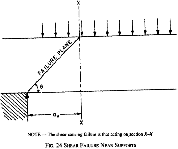
Figure description:
FIG. 24 SHEAR FAILURE NEAR SUPPORTS
- Failure Plane: A diagonal line originating from the support edge to the top surface at an angle .
- Section X-X: A vertical critical section located at a distance from the face of the support.
- Loading: Uniformly distributed downward loads applied to the top surface.
- Key Note: The shear force responsible for failure is the one acting specifically on section X-X.
similarly web reinforcement is determined for a fictitious shear which is a function of actual shear and torsion.
41.1.1
The design rules laid down in 41.3 and 41.4 shall apply to beams of solid rectangular cross-section. However, these clauses may also be applied to flanged beams, by substituting for in which case they are generally conservative; therefore specialist literature may be referred to.
41.2 Critical Section
Sections located less than a distance , from the face of the support may be designed for the same torsion as computed at a distance , where is the effective depth.
41.3 Shear and Torsion
41.3.1 Equivalent Shear
Equivalent shear, , shall be calculated from the formula:
where
equivalent shear,
,
torsional moment, and
breadth of beam.
The equivalent nominal shear stress, in this case shall be calculated as given in 40.1, except for substituting by . The values of shall not exceed the values of given in Table 20.
41.3.2
If the equivalent nominal shear stress, does not exceed given in Table 19, minimum shear reinforcement shall be provided as per 26.5.1.6.
41.3.3
If exceeds given in Table 19, both longitudinal and transverse reinforcement shall be provided in accordance with 41.4.
41.4 Reinforcement in Members Subjected to Torsion
41.4.1
Reinforcement for torsion, when required, shall consist of longitudinal and transverse reinforcement.
41.4.2 Longitudinal Reinforcement
The longitudinal reinforcement shall be designed to resist an equivalent bending moment, , given by
where
bending moment at the cross-section, and
where
is the torsional moment, is the overall depth of the beam and is the breadth of the beam.
41.4.2.1
If the numerical value of as defined in 41.4.2 exceeds the numerical value of the moment , longitudinal reinforcement shall be provided on the flexural compression face, such that the beam can also withstand an equivalent given by , the moment being taken as acting in the opposite sense to the moment
41.4.3 Transverse Reinforcement
Two legged closed hoops enclosing the corner longitudinal bars shall have an area of cross-section , given by
but the total transverse reinforcement shall not be less
but the total transverse reinforcement shall not be less than
where
- torsional moment,
- shear force,
- spacing of the stirrup reinforcement,
- centre-to-centre distance between corner bars.
- breadth of the member,
f.
unidentified
- characteristic strength of the stirrup reinforcement,
- = shear strength of the concrete as per Table 19.