27.1
Structures in which marked changes in plan dimensions take place abruptly shall be provided with expansion on joints at the section where such change occur. Expansion joints shall be so provided that the necessary movement occurs with a minimum resistance at the joint. The structures adjacent to the joint should preferably be supported on separate columns or walls but not necessarily on separate foundations. Reinforcement shall not extend across an expansion joint and the break between the section shall be complete.
27.2
The details as to the length of a structure where expansion joints have to be provided can be determine after taking into consideration various factors, such as temperature, exposure to weather, the time and season of the laying of the concrete, etc. Normally structures exceeding 45 m in length are designed with one or more expansion joints. However in view of the large number of factors involved in deciding the location spacing and nature of expansion joints, the provision of expansion joint in reinforced cement concrete structures should be left to the discretion of the designer. IS 3414 gives the design considerations which need to be examined and provided for.
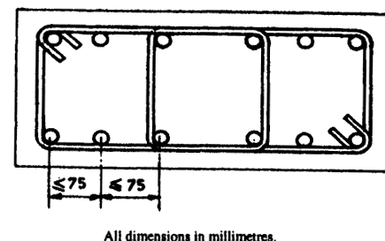
Figure description:
- Subject: Engineering diagram showing reinforcement detailing for a concrete member (cross-section.
- Components: Eight longitudinal reinforcement bars (circular enclosed by multiple overlapping transverse stirrups/links.
- Key Dimension: Spacing between longitudinal bars is specified as mm.
- Units: All dimensions are in millimetres.
Fig.
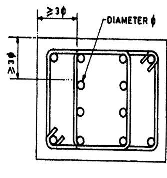
Figure description:
- Entity: Reinforced concrete column cross-section.
- Key Components:
- Main reinforcement: 10 longitudinal bars represented by circles.
- Ties/Stirrups: Rectangular and internal rectangular links securing the bars.
- Dimensional Constraints:
- Vertical spacing: (measured from center of corner bar to center of next bar.
- Horizontal spacing: (measured from center of corner bar to center of next bar.
- Notation: represents the diameter of the reinforcement bar.
- Units: All dimensions in millimetres.
All dimensions in millimetres.
Fig. 10
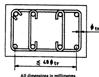
Figure description:
Technical diagram of a reinforced concrete cross-section:
- Entities:
- Longitudinal Reinforcement: 8 circular bars arranged in two rows of four.
- Transverse Reinforcement: Includes an outer perimeter stirrup and two internal vertical crossties.
- Key Dimensions & Notations:
- : Represents the diameter of the transverse reinforcement.
- Spacing Constraint: The horizontal distance between outer vertical legs is specified as .
- Units: All dimensions are in millimetres.
Fig.
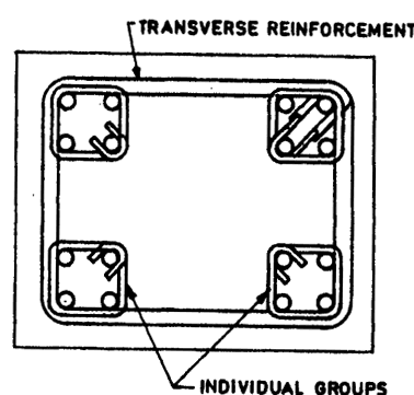
Figure description:
- Entity: Cross-section diagram of a reinforced structure (likely a concrete column.
- Transverse Reinforcement: A primary outer rectangular tie or hoop surrounding the internal components.
- Individual Groups: Four separate reinforcement clusters located at the corners of the main enclosure.
- Components per Group: Each group contains four longitudinal bars (circular elements bound by a smaller internal rectangular tie.
Fig. 1