E-1
In the absence of more exact analysis, the effective length of columns in framed structures may be obtained from the ratio of effective length to unsupported length given in Fig. 26 when relative displacement of the ends of the column is prevented and in Fig. 26 when relative lateral displacement of the ends is not prevented. In the latter case, it is recommended that the effective length ratio may not be taken to be less than 1.2 .
NOTE
- 1 Figures 26 and 27 are reproduced from 'The Structural Engineer' No. 7, Volume 52, July 1974 by the permission of the Council of the Institution of Structural Engineers U.K.
ΣK
- 2 In Figs. 26 and 27, and are equal to
where the summation is to be done for the member framing into a joint at top and bottom respectively; and and being the flexural stiffness for column and beam respectively.
E-2
To determine whether a column is a no sway or a sway column, stability index Q may be computed as given below:
where
- Δe = elastically computed first order lateral deflection.
- total lateral force acting within the storey
- height of the storey
If , then the column in the frame may be taken as no sway column, otherwise the column will be considered as sway column.
E-3
For normal usage assuming idealized conditions the effective length of in a given plane may be assessed on the basis of Table 28.
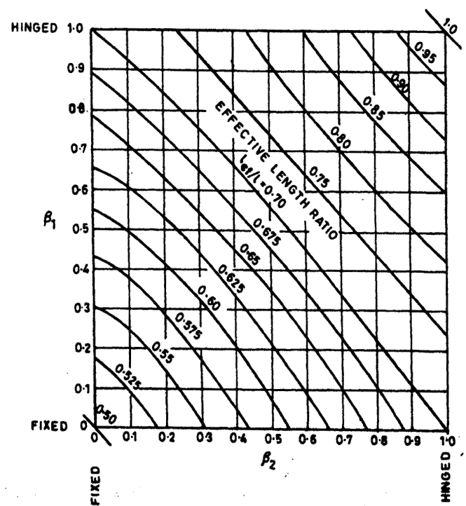
Figure description:
EFFECTIVE LENGTH RATIO l_ef/l
EFFECTIVE LENGTH RATIO l_ef/l
Annotations
- FIXED (text_label - position: beta_1 = 0, beta_2 = 0)
- HINGED (text_label - position: beta_1 = 1.0, beta_2 = 1.0)
- EFFECTIVE LENGTH RATIO l_ef/l (text_label - position: Center of plot area)
| Effective Length Ratio (l_ef / l) | beta_1 | beta_2 |
|---|---|---|
| 0.50 | 0.00 | 0.00 |
| 0.525 | 0.16 | 0.00 |
| 0.525 | 0.08 | 0.08 |
| 0.525 | 0.00 | 0.16 |
| 0.55 | 0.33 | 0.00 |
| 0.55 | 0.17 | 0.17 |
| 0.55 | 0.00 | 0.33 |
| 0.575 | 0.47 | 0.00 |
| 0.575 | 0.24 | 0.24 |
| 0.575 | 0.00 | 0.47 |
| 0.60 | 0.59 | 0.00 |
| 0.60 | 0.30 | 0.30 |
| 0.60 | 0.00 | 0.59 |
| 0.625 | 0.72 | 0.00 |
| 0.625 | 0.36 | 0.36 |
| 0.625 | 0.00 | 0.72 |
| 0.65 | 0.83 | 0.00 |
| 0.65 | 0.42 | 0.42 |
| 0.65 | 0.00 | 0.83 |
| 0.675 | 0.96 | 0.00 |
| 0.675 | 0.48 | 0.48 |
| 0.675 | 0.00 | 0.96 |
| 0.70 | 1.00 | 0.15 |
| 0.70 | 0.55 | 0.55 |
| 0.70 | 0.15 | 1.00 |
| 0.75 | 1.00 | 0.43 |
| 0.75 | 0.65 | 0.65 |
| 0.75 | 0.43 | 1.00 |
| 0.80 | 1.00 | 0.62 |
| 0.80 | 0.78 | 0.78 |
| 0.80 | 0.62 | 1.00 |
| 0.85 | 1.00 | 0.78 |
| 0.85 | 0.87 | 0.87 |
| 0.85 | 0.78 | 1.00 |
| 0.90 | 1.00 | 0.88 |
| 0.90 | 0.93 | 0.93 |
| 0.90 | 0.88 | 1.00 |
| 0.95 | 1.00 | 0.95 |
| 0.95 | 0.97 | 0.97 |
| 0.95 | 0.95 | 1.00 |
| 1.00 | 1.00 | 1.00 |
Notes: The chart is a nomogram used to determine the effective length ratio of a column or beam based on end restraint parameters beta_1 and beta_2. Both axes range from 0 (Fixed to 1.0 (Hinged. The curves are symmetrical about the line beta_1 = beta_2.))
FIG. 26 EFFECTIVE LENGTH RATIOS FOR A COLUMN IN A FRAME WITH NO SWAY
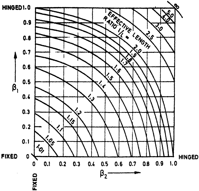
Figure description:
Effective Length Factor Nomogram for Unbraced Columns
Relationship between β1, β2 and Effective Length Ratio l/L
Legend
- Isolines of Effective Length Ratio (l/L — color: black; symbol: solid curve
Annotations
- HINGED (text_label - position: β1 = 1.0)
- FIXED (text_label - position: β1 = 0)
- HINGED (text_label - position: β2 = 1.0)
- FIXED (text_label - position: β2 = 0)
- EFFECTIVE LENGTH RATIO l/L = (text_label - position: interior label)
| Effective Length Ratio (l/L) | β2 | β1 |
|---|---|---|
| 1.01 | 0.00 | 0.05 |
| 1.01 | 0.02 | 0.02 |
| 1.01 | 0.05 | 0.00 |
| 1.05 | 0.00 | 0.17 |
| 1.05 | 0.08 | 0.08 |
| 1.05 | 0.17 | 0.00 |
| 1.10 | 0.00 | 0.31 |
| 1.10 | 0.15 | 0.15 |
| 1.10 | 0.31 | 0.00 |
| 1.15 | 0.00 | 0.43 |
| 1.15 | 0.21 | 0.21 |
| 1.15 | 0.43 | 0.00 |
| 1.20 | 0.00 | 0.54 |
| 1.20 | 0.27 | 0.27 |
| 1.20 | 0.54 | 0.00 |
| 1.30 | 0.00 | 0.70 |
| 1.30 | 0.38 | 0.38 |
| 1.30 | 0.70 | 0.00 |
| 1.40 | 0.00 | 0.81 |
| 1.40 | 0.48 | 0.48 |
| 1.40 | 0.81 | 0.00 |
| 1.50 | 0.00 | 0.88 |
| 1.50 | 0.56 | 0.56 |
| 1.50 | 0.88 | 0.00 |
| 1.60 | 0.00 | 0.93 |
| 1.60 | 0.63 | 0.63 |
| 1.60 | 0.93 | 0.00 |
| 1.70 | 0.00 | 0.96 |
| 1.70 | 0.69 | 0.69 |
| 1.70 | 0.96 | 0.00 |
| 1.80 | 0.00 | 0.98 |
| 1.80 | 0.74 | 0.74 |
| 1.80 | 0.98 | 0.00 |
| 1.90 | 0.00 | 0.99 |
| 1.90 | 0.78 | 0.78 |
| 1.90 | 0.99 | 0.00 |
| 2.00 | 0.00 | 1.00 |
| 2.00 | 0.81 | 0.81 |
| 2.00 | 1.00 | 0.00 |
| 2.5 | 0.64 | 1.00 |
| 2.5 | 0.915 | 0.915 |
| 2.5 | 1.00 | 0.64 |
| 3.0 | 0.80 | 1.00 |
| 3.0 | 0.955 | 0.955 |
| 3.0 | 1.00 | 0.80 |
| 4.0 | 0.91 | 1.00 |
| 4.0 | 0.98 | 0.98 |
| 4.0 | 1.00 | 0.91 |
| 5.0 | 0.95 | 1.00 |
| 5.0 | 0.99 | 0.99 |
| 5.0 | 1.00 | 0.95 |
| ∞ | 1.00 | 1.00 |
Notes: The chart represents the relationship for columns in unbraced frames where sidesway is permitted. β=0 corresponds to a perfectly fixed end, and β=1 corresponds to a perfectly hinged end.
FIG. 27 EFFECTIVE LENGTH RATIOS FOR A COLUMN IN A FRAME WITHOUT RESTRAINT AGAINST SWAY
Table 28 Effective Length of Compression Members
(Clause B-3)
| Degree of End Restraint of Compre- ssion Members | Symbol | Theoretical Value of Effective Length | Recommended Value of Effective Length |
|---|---|---|---|
| (1) | (2) | (3) | (4) |
| Effectively held in position and restrained against rotation in both ends | 0.50 / | 0.65 / | |
| Effectively held in position at both ends, restrained against rotation at one end | 0.70 / | 0.80 / | |
| Effectively held in position at both ends, but not restrained against rotation | 1.00 / | 1.00 / | |
| Effectively held in position and restrained against rotation at one end, and at the other restrained against rotation but not held in position | 1.00 / | 1.20 / | |
| Effectively held in position and restrained against rotation in one end, and at the other partially restr-ained against rotation but not held in position | - | 1.50 / | |
| Effectively held in position at one end but not restrained against rotation, and at the other end restrained against rotation but not held in position | 2.00 / | 2.00 / | |
| Effectively held in position and restrained against rotation at one end but not held in position nor restrained against rotation at the other end | 2.00 / | 2.00 / |
NOTE - / is the unsupported length of compression member.