25.1 Definitions
25.1.1
Column or strut is a compression member, the effective length of which exceeds three times the least lateral dimension.
25.1.2 Short and Slender Compression Members
A compression member may be considered as short when both the slenderness ratios and are less
than 12:
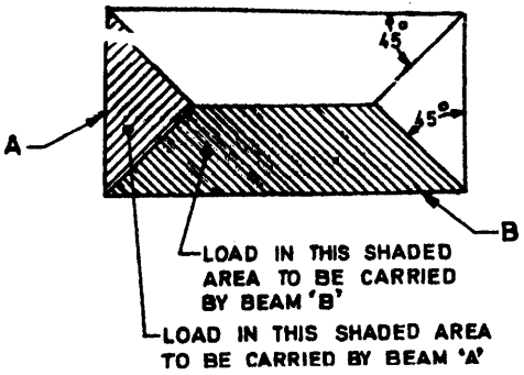
Figure description:
Subject: FIG. 7 LOAD CARRIED BY SUPPORTING BEAMS - A diagram showing load distribution from a rectangular slab to its perimeter beams.
Key Entities and Information:
- Beam 'A' (Short Side: Supports the load from the triangular shaded area at the slab's end.
- Beam 'B' (Long Side: Supports the load from the trapezoidal shaded area along the slab's length.
- Distribution Method: Load areas are determined by drawing lines from each corner at 45° angles.
- Load Shapes: The shorter beams carry triangular loads, while the longer beams carry trapezoidal loads.
FIG. 7 LOAD CARRIED BY SUPPORTING BEAMS
where
l
- effective length in respect of the major axis,
- depth in respect of the major axis,
- axis, and = width of the member.
It shall otherwise be considered as a slender compression member,
25.1.3 Unsupported Length
The unsupported length, l, of a compression member shall be taken as the clear distance between end restraints except that:
- a) in flat slab construction, it shall be clear distance between the floor and the lower extremity of the capital, the drop panel or slab whichever is the least.
- b) in beam and slab construction, it shall be the clear distance between the floor and the underside of the shallower beam framing into the columns in each direction at the next higher floor level.
- c) in columns restrained laterally by struts, it shall be the clear distance between consecutive struts in each vertical plane, provided that to be an adequate support, two such struts shall meet the columns at approximately the same level and the angle between vertical planes through the struts shall not vary more than 30" from a right angle. Such struts shall be of adequate dimensions and shall have sufficient anchorage to restrain the member against lateral deflection.
- d) in columns restrained laterally by struts or beams, with brackets used at the junction, it shall be the clear distance between the floor and the lower edge of the bracket, provided that the bracket width equals that of the beam strut and is at least half that of the column.
25.2 Effective Length of Compression Members
In the absence of more exact analysis, the effective length of columns may be obtained as described in Annex E.
25.3 Slenderness Limits for Columns
25.3.1
The unsupported length between end restraints shall not exceed 60 times the least lateral dimension of a column.
25.3.2
If, in any given plane, one end of a column is unrestrained, its unsupported length, , shall not exceed
100b²
D
where
- width of that cross-section, and
- depth of the cross-section measured in the plane under consideration.
25.4 Minimum Eccentricity
All columns shall be designed for minimum eccentricity, equal to the unsupported length of column/500 plus lateral dimensions/30, subject to a minimum of 20 mm. Where bi-axial bending is considered, it is sufficient to ensure that eccentricity exceeds the minimum about one axis at a time.