21.1
A structure or structural element required to have fire resistance should be designed to possess an appropriate degree of resistance to flame penetration; heat transmission and failure. The fire resistance of a structural element is expressed in terms of time in hours in accordance with IS 1641. Fire resistance of concrete elements depends upon details of member size, cover to steel reinforcement detailing and type of aggregate (normal weight or light weight) used in concrete. General requirements for fire protection are given in IS 1642.
21.2
Minimum requirements of concrete cover and member dimensions for normal-weight aggregate concrete members so as to have the required fire resistance shall be in accordance with 26.4.3 and Fig. 1 respectively.
21.3
The reinforcement detailing should reflect the changing pattern of the structural section and ensure that both individual elements and the structure as a whole contain adequate support, ties, bonds and anchorages for the required fire resistance.
21.3.1
Additional measures such as application of fire resistant finishes, provision of fire resistant false ceilings and sacrificial steel in tensile zone, should be adopted in case the nominal cover required exceeds 40 mm for beams and 35 mm for slabs, to give protection against spalling.
21.4
Specialist literature may be referred to for determining fire resistance of the structures which have not been covered in Fig. 1 or Table 16A.
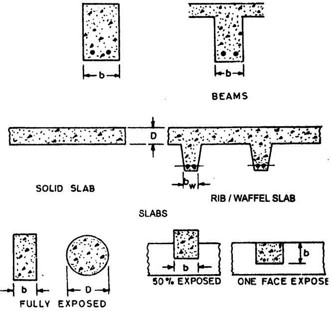
Figure description:
Columns
- Rectangular Column: Width dimension indicated as .
- T-Shaped Column: Base width dimension indicated as .
Beams
- Solid Slab: Thickness dimension indicated as .
- Rib / Waffle Slab: Rib width dimension indicated as .
Slabs (Exposure Categories
- Fully Exposed: Includes a rectangular section (width and a circular section (diameter .
- 50% Exposed: A rectangular section partially embedded in a structure (width .
- One Face Exposed: A rectangular section mostly embedded, with one side surface exposed (dimension .
COLUMNS
| Fire Resis- tance h | Minimum Beam Width b | Rib Width of Slabs bw | Minimum Thickness of Floors D | Column Dimension (b or D) | Minimum Wall Thickness | ||||
|---|---|---|---|---|---|---|---|---|---|
| Fully Exposed | 50% Exposed | One Face Exposed | p<0.4% | 0.4%≤p≤1% | p>1% | ||||
| mm | mm | mm | mm | mm | mm | mm | mm | mm | |
| 0.5 | 200 | 125 | 75 | 150 | 125 | 100 | 150 | 100 | 100 |
| 1 | 200 | 125 | 95 | 200 | 160 | 120 | 150 | 120 | 100 |
| 1.5 | 200 | 125 | 110 | 250 | 200 | 140 | 175 | 140 | 100 |
| 2 | 200 | 125 | 125 | 300 | 200 | 160 | - | 160 | 100 |
| 3 | 240 | 150 | 150 | 400 | 300 | 200 | - | 200 | 150 |
| 4 | 280 | 175 | 170 | 450 | 350 | 240 | - | 240 | 180 |
NOTES
1 These minimum dimensions relate specifically to the covers given in Table 16A.
2 p is the percentage of steel reinforcement.
FIG. 1 MINIMUM DIMENSIONS OF REINFORCED CONCRETE MEMBERS FOR FIRE RESISTANCE