Erection tolerances shall be defined relative to member working points and working lines, which shall be defined as follows:
- (a) For members other than horizontal members, the member work point shall be the actual center of the member at each end of the shipping piece.
- (b) For horizontal members, the working point shall be the actual centerline of the top flange or top surface at each end.
- (c) The member working line shall be the straight line that connects the member working points.
Commentary
The provision (b) applies at the “top flange” or “top surface” of a horizontal member. It should be noted that this may not be the uppermost point of members, such as trusses with W-shape chords with webs horizontal or trusses with chords skewed from square. The contract documents may specify alternative working points.
The substitution of other working points is permitted for ease of use.
The tolerances on structural steel erection shall be in conformance with the requirements in Sections 11.3.1.
Commentary
The erection tolerances defined in this section have been developed through long standing usage as practical criteria for the erection of structural steel. Erection tolerances were first defined in the 1924 edition of this Code in Section 7(f), “Plumbing Up.” With the changes that took place in the types and use of materials in building construction after World War II, and the increasing demand by architects and owners for more specific tolerances, AISC adopted new standards for erection tolerances in Section 7(h) of the March 15, 1959, edition of this Code. Experience has proven that those tolerances can be economically obtained.
Differential column shortening may be a consideration in design and construction. In some cases, it may occur due to variability in the accumulation of dead load among different columns (see Figure C-11.3). In other cases, it may be characteristic of the structural system that is employed in the design. Consideration of the effects of differential column shortening may be very important, such as when the slab thickness is reduced, when electrical and other similar fittings mounted on the structural steel are intended to be flush with the finished floor, and when there is little clearance between bottoms of beams and the tops of door frames or ductwork.
The effects of the deflection of transfer girders and trusses on the position of columns and hangers supported from them may be a consideration in design and construction. As in the case of differential column shortening, the deflection of these supporting members during and after construction will affect the position and alignment of the framing tributary to these transfer members.
Expansion and contraction in a structural steel frame may be a consideration in design and construction. Steel will expand or contract approximately 1/8 in. per 100 ft for each change of 15°F (3 mm per 30 m for each change of 8.3°C)
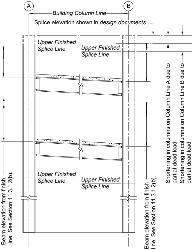
Figure description:
Figure C-11.3: Effects of differential column shortening
- Key Entities: Building Column Lines A and B, connecting beams, floor slabs, and splice lines.
- Structural Details:
- Column Shortening: Illustrates vertical compression in columns due to partial dead loads on both Line A and Line B.
- Differential Movement: Shows Column B shortening more than Column A, resulting in non-horizontal (sloping beams and floor slabs.
- Splice Elevations: Distinguishes between the theoretical splice elevation in design documents and the actual "Upper Finished Splice Line" after loading.
- Measurement: Beam elevations are referenced from a finish line per Section 11.3.1.2(b.
Fig. C-11.3. Effects of differential column shortening.
in temperature. This change in length can be assumed to act about the center of rigidity. When anchored to their foundations, end columns will be plumb only when the steel is at normal temperature (see Figure C-11.4). It is therefore necessary to correct field measurements of offsets to the structure from established baselines for the expansion or contraction of the exposed structural steel frame. For example, a 200-ft-long (61-m-long) building that is plumbed up at 100°F (38°C) should have working points at the tops of the end columns positioned ½ in. (13 mm) further apart than the working points at the corresponding bases in order for the columns to be plumb at 70°F (21°C). Differential temperature effects on column length should also be taken into account in plumbing surveys when tall structural steel frames are subjected to sun exposure on one side.
The Code does not provide explicit tolerances for the vertical position of the top of column shipping pieces at the tier splices in a multi-story frame. The design and construction teams need to establish requirements for monitoring the vertical position of the tier splices. Performance requirements should be addressed in the contract documents. The means of making adjustments should be addressed by pre-planning and mutual agreement among the affected parties prior to the commencement of fabrication and erection.
The alignment of lintels, spandrels, wall supports, and similar members that are used to connect other building construction units to the structural steel frame should have an adjustment of sufficient magnitude to allow for the accumulation of mill tolerances and fabrication tolerances, as well as the erection tolerances. See Figure C-11.5.
If the engineer of record determines that additional tolerances are required by the design concept, the tolerances should be identified in the contract documents, as required by Section 1.11 and ANSI/AISC 360, Section A4.1. The tolerances should be expressed in terms consistent with those found in Section 11, i.e., a description of the parameter to be measured and a tolerance (acceptable deviation from the required parameter).
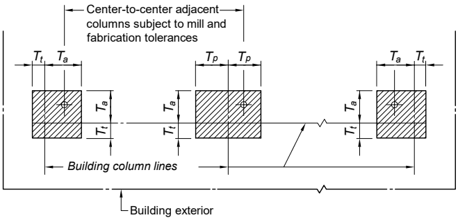
Figure description:
This diagram (Fig. C-11.4 illustrates the engineering tolerances for column plan locations relative to building column lines and the building exterior.
Key Entities and Parameters:
- Building Column Lines: The primary reference axes for the placement of structural columns.
- Building Exterior: The outer boundary reference line for the structure.
- : Tolerance for the location of the column cross-section relative to the column lines.
- : Tolerance associated with the total offset or thickness variation.
- : Plan location tolerance for adjacent columns.
- Center-to-Center Adjacent Columns: A measurement subject to both mill and fabrication tolerances.
- Shaded Rectangles: Represent the cross-sections of the columns within their allowable tolerance zones.
Fig. C-11.4. Tolerances in plan location of column.
Tolerances for Complex Structures. During successive stages of erection, certain complex steel framed structures may require significant temporary support, bracing, and/or means to maintain geometry and stability during erection to mitigate substantial displacement or indeterminate load paths. These conditions may arise due to the planned sequential application of dead loads, including nonstructural steel elements, during or after completion of the erection of the steel frame. Some examples include, but are not limited to, structures that have nonstructural steel elements in their lateral force-resisting system, structures incorporating cable elements, long span and cantilevered structures, two-way girder or truss-framed structures, and inclined steel frames.
In order to achieve the specified plumb condition, elevation, and alignment of the structure at the completion of the erector’s work, and to determine the necessary fabrication geometry and preset geometry (camber or super-elevation) during erection of these structures, an analytical three-dimensional model should be used by the fabricator/erector to perform a staged construction analysis and erection bracing drawings.
The determination of the fabrication geometry, any preset geometry, and the unstressed and stressed conditions of the steel frame is best achieved through a cooperative approach between the fabricator/erector and the owner's designated representative for design. The fabricator/erector should be provided with the same loads and the sequence of application of those loads used by the
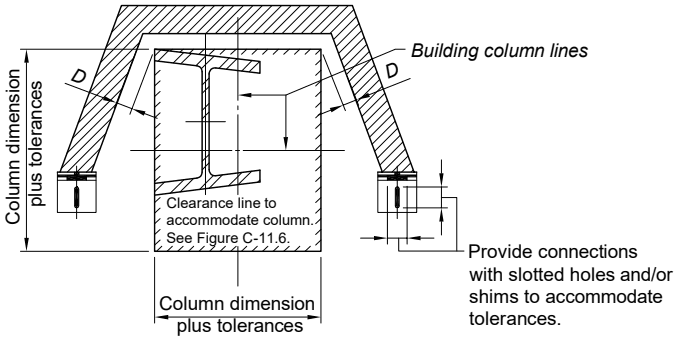
Figure description:
The image is a technical diagram showing structural steel column clearances and connection details.
Key Entities and Information:
- Column Profile: A steel I-beam located within a defined clearance area.
- Clearance Line: A rectangular hatched boundary labeled "Clearance line to accommodate column" (references Figure C-11.6.
- Building Column Lines: Reference centerlines for the structural layout.
- Dimensions:
- D: Offset distance between building column lines and the clearance boundary.
- Column dimension plus tolerances: Specified for both the width and depth of the clearance zone.
- Connection Detail: Notes specify providing connections with slotted holes and/or shims to accommodate fabrication and erection tolerances.
If facia joints are set from nearest column finish line, allow ±5/8 in. (16 mm) for vertical adjustment. The entity responsible for the facia details must allow for progressive shortening of steel columns.
D = Tolerance required by manufacturer of wall unit plus survey tolerances.
Fig. C-11.5. Clearance required to accommodate fascia.
owner's designated representative for design. The owner's designated representative for construction should also provide a schedule for the application of the loads cited above for use in the creation of the erection bracing drawings.
Before commencing the work, the fabricator/erector and the owner’s designated representative for construction must mutually agree as to how and when the requirements of Section 11.3 will be applied.
11.3.1
The tolerances on position and alignment of member working points and working lines shall be as described in Sections 11.3.1.1 through 11.3.1.3.
11.3.1.1
For an individual column shipping piece intended to be vertical, the angular variation of the working line from a plumb line shall be equal to or less than 1/500 of the distance between working points, subject to the following additional limitations:
- (a) For an individual column, the allowed horizontal variation in location from the specified position at the base shall be equal to or less than ¼ in. (6 mm) in any direction.
- (b) At column splices the variation between the upper column centerline relative to each principal axis and the lower column centerline relative to each principal axis shall be plus or minus 1/4 in. (6 mm).
- (c) For an individual column shipping piece that is adjacent to an elevator shaft, the displacement of member working points shall be equal to or less than 1 in. (25 mm) from the building column line in the first 20 stories. Above this level, an increase in the displacement of 1/32 in. (1 mm) is permitted for each additional story up to a maximum displacement of 2 in. (50 mm) from the building column line.
- (d) For an exterior individual column shipping piece, the displacement of member working points from the building column line in the first 20 stories shall be equal to or less than 1 in. (25 mm) toward and 2 in. (50 mm) away from the building exterior. Above this level, an increase in the displacement of 1/16 in. (2 mm) is permitted for each additional story up to a maximum displacement of 2 in. (50 mm) toward and 3 in. (75 mm) away from the building exterior.
Commentary
The limitations that are described in this section and illustrated in Figures C-11.6 and C-11.7 make it possible to maintain built-in-place or prefabricated facades in a true vertical plane up to the 20th story, if connections that provide for 3 in. (75 mm) of adjustment are used. Above the 20th story, the facade may be maintained within 1/16 in. (2 mm) per story with a maximum total deviation of 1 in. (25 mm) from a true vertical plane, if connections that provide for 3 in. (75 mm) of adjustment are used. Connections that permit adjustments of plus 2 in. (50 mm) to minus 3 in. (75 mm)—a total of 5 in. (125 mm)—will be necessary in cases where it is desired to construct the facade to a true vertical plane above the 20th story.
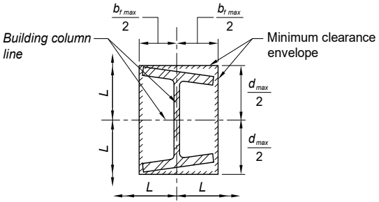
Figure description:
Key Entities & Details:
- Building Column: Represented by an I-beam cross-section.
- Building Column Line: Vertical and horizontal centerlines used as reference axes.
- Minimum Clearance Envelope: A cross-hatched rectangular region defining the required space around the column for enclosures or attachments.
- Dimensions:
- Width: Defined as or from the vertical centerline.
- Depth/Height: Defined as or from the horizontal centerline.
For Enclosures or Attachments That May Follow Column Alignment
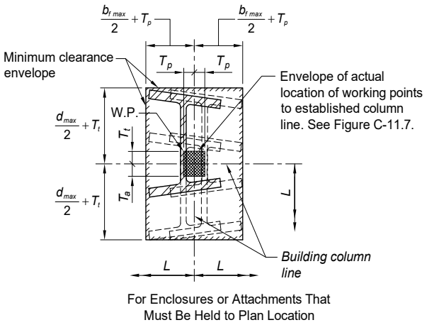
Figure description:
This technical diagram illustrates structural clearance envelopes for building column alignments and plan locations.
Key Entities and Dimensions
- Building Column: An I-beam cross-section shown in various possible shifted and tilted orientations.
- Minimum Clearance Envelope: A rectangular hatched boundary defining the required space around the column.
- W.P. (Working Point: The central reference point on the column web.
- Building Column Line: Horizontal and vertical centerlines used as the established reference grid.
- Envelope of actual location of working points: A central shaded rectangular area representing the tolerance range for the working point relative to the column line.
Defined Variables
- : Maximum depth of the column.
- : Maximum flange width of the column.
- : Horizontal tolerance dimension.
- / : Vertical tolerance dimensions for working point location.
- : Offset distance from the building column line to the envelope boundary.
- Vertical Boundary Formulas:
- Horizontal Boundary Formulas:
- Actual center-to-center of columns plan dimensions column cross-section
- tolerance of columns ± beam length tolerance
- Plumbness tolerance away from building exterior (varies, see Figure C-11.7)
- Plumbness tolerance toward building exterior (varies, see Figure C-11.7)
- Plumbness tolerance parallel to building exterior
Notes:
-
and per ASTM A6/A6M. See Figure C-5.1.
-
The maximum clearance envelope does not include permissible sweep and camber in the column material.
Fig. C-11.6. Clearance required to accommodate accumulated column tolerance.
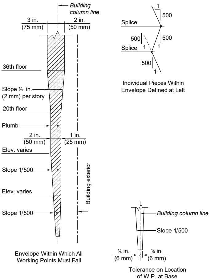
Figure description:
Key Information: Column Plumbness and Location Tolerances
Main Diagram: Envelope for Working Points (W.P.
- Building Column Line: Central reference vertical line.
- Total Allowable Deviation (Top: 3 in. (75 mm toward building exterior; 2 in. (50 mm away from exterior at 36th floor.
- Intermediate Slope: in. (2 mm per story between 20th and 36th floors.
- Mid-level Deviation (20th floor: 2 in. (50 mm toward exterior; 1 in. (25 mm away from exterior.
- Lower Slopes: Specified as 1/500 relative to the building column line.
- Building Exterior: Indicated to the right of the column line.
Individual Pieces Diagram (Top Right
- Slope Tolerance: Individual column segments between splices must maintain a 1/500 slope.
- Splice Points: Working points must remain within the defined envelope.
Base Location Tolerance (Bottom Right
- Tolerance on Location of W.P. at Base: in. (6 mm from the building column line.
- Initial Slope: 1/500.
Note: The plumb line through the base working point for an individual column is not necessarily the precise plan location because Section 11.3.1.1 deals only with plumbness tolerances and does not include inaccuracies in location of the building column line, foundations, and anchor rods beyond the erector's model.
Fig. C-11.7. Exterior column plumbness tolerances normal to building line.
- (e) For an exterior individual column shipping piece, the member working points at any splice level for multi-tier buildings and at the tops of columns for single-tier buildings shall fall within a horizontal envelope, parallel to the exterior building column line, that is equal to or less than 1½ in. (38 mm) wide for buildings up to 300 ft (91 m) in length. An increase in the width of this horizontal envelope of ½ in. (13 mm) is permitted for each additional 100 ft (30 m) in length up to a maximum width of 3 in. (75 mm).
Commentary
This section limits the position of exterior column working points at any given splice elevation to a narrow horizontal envelope parallel to the exterior building column line (see Figure C-11.8). This envelope is limited to a width of 1½ in. (38 mm), normal to the exterior building column line, in up to 300 ft (90 000 mm) of building length. The horizontal location of this envelope is not necessarily directly above or below the corresponding envelope at the adjacent splice elevations but should be within the limitation of the 1 in 500 plumbness tolerance specified for the controlling columns (see Figure C-11.7).
- (f) For an exterior column shipping piece, the displacement of member working points from the building column line that is nominally parallel to the building exterior shall be equal to or less than 2 in. (50 mm) in the first 20 stories. Above this level, an increase in the displacement of 1/16 in. (2 mm) is permitted for each additional story up to a maximum displacement of 3 in. (75 mm) in the direction nominally parallel to the building exterior.
- (g) For columns bearing on transfer members such as transfer girders and trusses the reference line for column plumbness and position is located at the intersection of the conforming, as-erected center of the transfer member, and the orthogonal building column line.
Commentary
As illustrated in Figure C-11.8, the position tolerance for a column bearing on a transfer member is measured at the column location from the transfer member centerline along its longitudinal axis and from the perpendicular building column line.
11.3.1.2
For members other than column shipping pieces, the following limitations shall apply:
-
(a) For a member that consists of an individual, straight shipping piece without field splices, other than a cantilevered member, the variation in alignment shall be acceptable if it is caused solely by variations in column alignment and/or primary supporting member alignment that are within the permissible variations for the fabrication and erection of such members.
-
(b) For a member that consists of an individual, straight shipping piece that connects to a column, the variation in the distance from the member working point to the upper finished splice line of the column shall be equal to or less than plus 3/16 in. (5 mm) and minus 5/16 in. (8 mm). These tolerances also apply at the top of a column, either the top column in a multi-tier building or a column in a single-tier building.
-
(c) For a member that consists of an individual shipping piece that does not connect to a column, the variation in elevation shall be acceptable if it is caused solely by the variations in the elevations of the supporting members within the permissible variations for the fabrication and erection of those members.
-
(d) For a member that consists of an individual, straight shipping piece and that is a segment of a field assembled unit containing field splices between points of support, the plumbness, elevation, and alignment shall be acceptable if the angular variation, vertically and horizontally, of the working line from a straight line between points of support is equal to or less than 1/500 of the distance between working points.
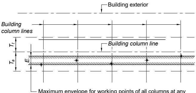
Figure description:
Key Information:
- Building Column Lines: Vertical and horizontal grid lines defining the structural layout.
- Building Exterior: Outer boundary line indicated above the column lines.
- Maximum Envelope (: A shaded horizontal zone representing the allowable tolerance for column working points.
- Working Points: Individual points plotted within or on the boundary of the envelope at the intersection of column lines.
- Tolerances (: Vertical dimensions indicating specific distance offsets or tolerance ranges relative to the building column line.
- Contextual Specification: in. (38 mm for lengths up to 300 ft (91 m; increases by in. (13 mm per 100 ft (30 m thereafter, capped at a 3 in. (75 mm total.
Maximum envelope for working points of all columns at any given elevation in. (38 mm) for up to 300 ft (91 m) of length; add in. (13 mm) for each 100 ft (30 m) of length with 3 in. (75 mm) max. total.
For column plumbness tolerance, see Figures C-11.6 and C-11.7.
- † Indicates column working points
At any splice elevation, envelope "E" is located within the limits and .
At any splice elevation, envelope "E" may be located offset from the corresponding envelope at the adjacent splice elevations, above and below, by an amount not greater than 1/500 of the column length.
Fig. C-11.8. Tolerances in plan at any splice elevation of exterior columns.
Commentary
The angular misalignment of the working line of all fabricated shipping pieces relative to the line between support points of the member as a whole in erected position must not exceed 1 in 500. Note that the tolerance is not stated in terms of a linear displacement at any point and is not to be taken as the overall length between supports divided by 500. Typical examples are shown in Figure C-11.9. Numerous conditions within tolerance for these and other cases are possible. The condition described in (d) applies to both plan and elevation tolerances.
- (e) For a cantilevered member that consists of an individual, straight shipping piece, the plumbness, elevation, and alignment shall be acceptable if the angular variation of the working line from a straight line that is extended in the plan direction from the working point at its supported end is equal to or less than 1/500 of the distance from the working point at the free end.
Commentary
This tolerance is evaluated after the fixed end condition is sufficient to stabilize the cantilever and before the temporary support is removed. The preset specified in the contract documents should be calculated accordingly. The temporary support cannot be used to induce artificial deflection into the cantilever to meet this tolerance after the fixed end is restrained.
- (f) For a member of irregular shape, the plumbness, elevation, and alignment shall be acceptable if the fabricated member is within its tolerances and the members that support it are within the tolerances specified in this Code.
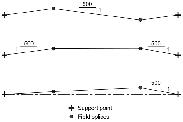
Figure description:
- Subject: Alignment tolerances for structural members with field splices.
- Key Entities:
- Support Points (+: Fixed end points of the member.
- Field Splices (●: Connection points between member segments.
- Critical Dimensions:
- Maximum slope tolerance is defined as 1:500 relative to the theoretical straight centerline.
- Visual Configurations:
- Top: Alternating deviation from centerline.
- Middle: Symmetrical deviation from centerline.
- Bottom: Progressive deviation across segments.
Fig. C-11.9. Alignment tolerances for members with field splices.
- (g) For a member that is fully assembled in the field in an unstressed condition, the same tolerances shall apply as if fully assembled in the shop.
- (h) For a member that is field-assembled, element-by-element, in place, temporary support shall be used or an alternative erection plan shall be submitted to the owner's designated representatives for design (ODRD) and construction (ODRC). The tolerance in Section 11.3.1.2(d) shall be met in the supported condition with working points taken at the point(s) of temporary support.
Commentary
Trusses fabricated and erected as a unit or as an assembly of truss segments normally have excellent controls on vertical position regardless of fabrication and erection techniques. However, a truss fabricated and erected by assembling individual components in place in the field is potentially more sensitive to deflections of the individual truss components and the partially completed work during erection, particularly the chord members. In such a case, the erection process should follow an erection plan that addresses this issue.
11.3.1.3
For members that are identified as adjustable items by the ODRD in the contract documents, the fabricator shall provide adjustable connections for these members to the supporting structural steel frame. Otherwise, the fabricator is permitted to provide nonadjustable connections. When adjustable items are specified, the ODRD shall indicate the total adjustability that is required for the proper alignment of these supports for other trades. The variation in the position and alignment of adjustable items shall be as follows:
- (a) The variation in the vertical distance from the upper finished splice line of the nearest column to the support location specified in the structural design documents shall be equal to or less than plus or minus 3/8 in. (10 mm).
- (b) The variation in the horizontal distance from the established finish line at the particular floor shall be equal to or less than plus or minus 3/8 in. (10 mm).
- (c) The variation in vertical and horizontal alignment at the abutting ends of adjustable items shall be equal to or less than plus or minus 3/16 in. (5 mm).
Commentary
When the alignment of lintels, wall supports, curb angles, mullions, and similar supporting members for the use of other trades is required to be closer than that permitted by the foregoing tolerances for structural steel, the ODRD must identify such items in the contract documents as adjustable items.
11.3.1.4
For inclined columns, the tolerances of 11.3.1.1(a), (c), (d), and (e) shall also apply at the working points of these columns.
11.3.2
In the design of steel structures, the ODRD shall provide for the necessary clearances and adjustments for material furnished by other trades to accommodate the mill tolerances, fabrication tolerances, and erection tolerances in this Code for the structural steel frame.
Commentary
In spite of all efforts to minimize inaccuracies, deviations will still exist; therefore, in addition, the designs of prefabricated wall panels, partition panels, fenestrations, floor-to-ceiling door frames, and similar elements must provide for clearance and details for adjustment as described in Section 11.3.2. Designs must provide for adjustment in the vertical dimension of prefabricated facade panels that are supported by the structural steel frame because the accumulation of shortening of loaded steel columns will result in the unstressed facade supported at each floor level being higher than the structural steel framing to which it must be attached. Observations in the field have shown that where a heavy facade is erected to a greater height on one side of a multistory building than on the other, the structural steel framing will be pulled out of alignment. Facades should be erected at a relatively uniform rate around the perimeter of the structure.
Metric Conversion Factors for Common Steel Design Units in AISC Specifications
| Unit | Multiply | by | to obtain |
|---|---|---|---|
| length | inch (in.) | 25.4 | millimeters (mm) |
| length | foot (ft) | 0.304 8 | meters (m) |
| mass | pound-mass (lbm) | 0.453 6 | kilogram (kg) |
| stress | ksi | 6.895 | megapascals (MPa), N/mm2 |
| moment | kip-in. | 113 000 | N-mm |
| energy | ft-lbf* | 1.356 | joule (J) |
| force | kip (1 000 lbf)* | 4 448 | newton (N) |
| force | psf | 47.88 | pascal (Pa), N/m2 |
| force | plf | 14.59 | N/m |
| force | kip/in. | 175.1 | N/mm |
| temperature | To convert °F to °C: tc° = (tf° - 32)/1.8 | ||
*Force in lbf or N = mass x g, where g, acceleration due to gravity = 32.2 ft/sec² = 9.81 m/sec²
Smarter. Stronger. Steel.
American Institute of Steel Construction 130 E Randolph St, Ste 2000 Chicago, IL 60601 312.670.2400 | www.aisc.org