The tolerances on structural steel fabrication shall be in conformance with the requirements in Section 11.2.1 through 11.2.8.
Commentary
Fabrication tolerances are stipulated in several specifications and codes, each applicable to a specialized area of construction. Basic fabrication tolerances are stipulated in this Section. For architecturally exposed structural steel, see Section 10. Other specifications and codes are also commonly incorporated by reference in the contract documents, such as ANSI/AISC 360, the RCSC Specification, AWS D1.1/D1.1M, AWS D1.5/D1.5M, AIST Technical Report 13, and the AASHTO Specification.
If the engineer of record determines that additional tolerances are required by the design concept, the tolerances should be identified in the contract documents, as required by Section 1.11 and ANSI/AISC 360, Section A4.1. The tolerances should be expressed in terms consistent with those found in Section 11, i.e., a description of the parameter to be measured and a tolerance (acceptable deviation from the required parameter).
11.2.1
For members that have both ends finished (see Section 6.2.2) for contact bearing, the variation in the overall length shall be equal to or less than 1/32 in. (1 mm). For other members that frame to other structural steel elements, the variation in the detailed length shall be as follows:
- (a) For members that are equal to or less than 30 ft (9.1 m) in length, the variation shall be equal to or less than 1/16 in. (2 mm).
- (b) For members that are greater than 30 ft (9.1 m) in length, the variation shall be equal to or less than 1/8 in. (3 mm).
11.2.2
For straight and curved structural members, whether of a single standard structural shape or built-up, the permitted variation in specified straightness or curvature shall be as listed in the following. In all cases, completed members shall be free of twists (except as allowed by ASTM standards), bends, and open joints. Sharp kinks or sharp bends shall be cause for rejection.
11.2.2.1
For straight structural members, the variation in straightness shall be equal to or less than that specified for structural shapes in the applicable ASTM standards except when a smaller variation is specified in the contract documents.
11.2.2.2
For curved structural members, the variation in the chord length shall be as defined in Section 11.2.1. The variation in curvature measured at the middle ordinate shall be equal to or less than the permissible variations in straightness as specified in applicable ASTM standards for camber in the strong direction and sweep in the weak direction, inside or outside of the theoretical arc, except when a smaller variation is specified in the contract documents. Should no applicable ASTM standard exist, the maximum variation in curvature measured at the middle ordinate shall be plus or minus 1/8 in. (3 mm) times one-fifth the total arc length in ft (times two-thirds the total arc length in m) for members 10 ft (3 m) or greater in length. For members less than 10 ft (3 m) in length, the permissible variation in curvature measured at the middle ordinate shall be plus or minus 1/8 in. (3 mm). The middle ordinate is located between work points (W.P.) as shown in Figure C-11.1.
For curved members, the work points shall be defined as follows:
- (a) For members other than horizontal members, the member work point shall be the actual center of the member at each end of the shipping piece.
- (b) For horizontal members, the work point shall be the actual centerline of the top flange or top surface at each end.
Commentary
Curved structural members, as referred to in this section, are defined as those members intended to maintain a specified curvature while in use. This section does not apply to members specified for camber. The location of the arc length is defined by the contract drawings and may be either at the member’s inside radius, the outside radius, or the radius between work points.
11.2.3
For beams that are detailed without specified camber, the member shall be fabricated so that, after erection, any incidental camber due to rolling or shop fabrication is upward. For trusses that are detailed without specified camber, the components shall be fabricated so that, after erection, any incidental camber in the truss due to rolling or shop fabrication is upward.
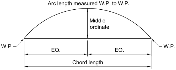
Figure description:
Fig. C-11.1. Illustration of the tolerance on curved structural steel member
- Arc length: Measured between the two Work Points (W.P..
- Chord length: The straight-line distance between the two W.P.s.
- Middle ordinate: The vertical measurement from the center of the chord to the highest point of the arc.
- W.P. (Work Points: The defined endpoints at each side of the curved member.
- EQ.: Indicates the chord length is bisected into two equal parts by the middle ordinate.
Fig. C-11.1. Illustration of the tolerance on curved structural steel member.
11.2.4
Beams specified in the contract documents as cambered, which are ordered as straight as defined by the applicable ASTM Specification and received by the fabricator with 75% of the specified camber, shall require no further cambering.
For beams specified in the contract documents as cambered, which are ordered as cambered or cambered by the fabricator, the variation in camber shall be as follows:
- (a) For beams that are detailed equal to or less than 50 ft (15 m) in length, the variation shall be equal to or less than minus zero/plus 1/2 in. (13 mm).
- (b) For beams that are detailed greater than 50 ft (15 m) in length, the variation shall be equal to or less than minus zero/plus ½ in. plus ⅛ in. for each 10 ft or fraction thereof (13 mm plus 3 mm for each 3 m or fraction thereof) in excess of 50 ft (15 m) in length.
For the purpose of inspection, camber shall be measured in the fabricator's shop in the unstressed condition.
Commentary
Camber can only be properly specified and inspected in the unstressed condition. Inspection is best performed in the shop using established quality control procedures where remedial work, if required, can easily be performed.
Camber cannot be inspected after erection because the effect of dead load and connection restraint cannot be accurately determined. See AISC Design Guide 36, Design Considerations for Camber, Appendix B.
The camber tolerance in this section applies to camber induced in the fabrication process, which is done in response to camber requirements in the contract documents.
In structural steel members there are two kinds of camber: (1) incidental camber, i.e., deviation from straightness, which is controlled by ASTM A6/A6M; and (2) induced camber which is specified by the engineer of record and is created by the fabricator or a supplier. Induced camber is controlled by the tolerances in Section 11.2.4. Straight members are subject to the straightness tolerances for sweep and camber in ASTM A6/A6M. AISC has recommended that designers not specify cambers that are less than in. to 1 in. (25 mm).
11.2.5
For fabricated trusses that are specified in the contract documents with camber, the variation in camber at each specified camber point shall be equal to or less than plus or minus 1/800 of the distance to that point from the nearest point of support. For the purpose of inspection, camber shall be measured in the unstressed condition. For fabricated trusses that are specified in the contract documents without indication of camber, the foregoing requirements shall be applied at each panel point of the truss with a zero camber ordinate.
Commentary
There is no known way to inspect truss camber in other than its “unstressed condition” because of factors that include the following:
- (a) The effects of the dead weight of the member
- (b) The restraint caused by the truss connections in the erected state
- (c) The effects of additional dead load that may ultimately be intended to be applied, if any
Therefore, for shop fabricated trusses, inspection of the fabricator's work on truss camber should be done in the fabrication shop in the unstressed condition. See Figure C-11.2. However, it is common practice for field assembled trusses to be ground assembled either in the laydown or shored position and the camber should be checked before raising the truss.
11.2.6
When permissible variations in the depths of beams and girders result in abrupt changes in depth at splices, such deviations shall be accounted for as follows:
- (a) For splices with bolted joints, the variations in depth shall be taken up with filler plates.
- (b) For splices with welded joints, the weld profile shall be adjusted to conform to the variations in depth, the required cross section of weld shall be provided, and the slope of the weld surface shall meet the requirements in AWS D1.1/D1.1M.
11.2.7
For holes in base and bearing plates, the allowable variation from the detailed location with respect to the column shaft centerlines shall be plus or minus 1/8 in. (3 mm).
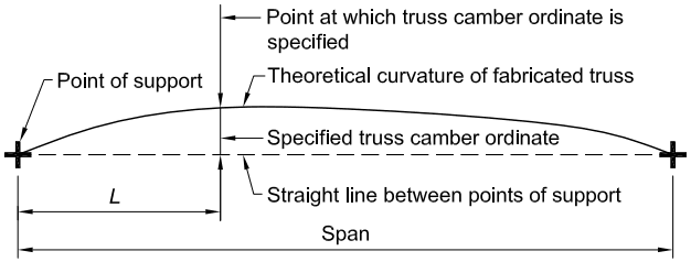
Figure description:
Technical Diagram: Truss Camber and Tolerance
Key Components:
- Theoretical Curvature: The curved path of the fabricated truss.
- Straight Line: Reference baseline between the two points of support.
- Specified Truss Camber Ordinate: The vertical measurement between the straight line and the theoretical curvature.
- Point of Support: The endpoints of the truss span.
- L: Horizontal distance from the closer support point to the measurement point.
- Span: Total distance between support points.
Specifications:
- Constraint: must be equal to or less than one-half the span.
- Tolerance Formula: The tolerance for the camber ordinate at distance is calculated as .
Taking L as the distance from the point at which truss camber is specified to the closer point of support, in. (mm), the tolerance on truss camber at that point is calculated as L/800. L must be equal to or less than one-half the span.
Fig. C-11.2. Illustration of the tolerance on camber for fabricated trusses with specified camber.
11.2.8
The tolerance on overall profile dimensions of welded built-up members shall meet the requirements in AWS D1.1/D1.1M and AWS D1.8/D1.8M for buildings, and AWS D1.5M/D1.5 for bridges.