Dimensions and properties for each shape are listed sequentially in a single row. The data in each column is as follows:
| Column in Database[a] | Variable | Description[a] |
|---|---|---|
| A | Type | Shape type: W, M, S, HP, C, MC, L, WT, MT, ST, 2L, HSS, PIPE |
| B (CG) | EDI_STD_ Nomenclature | The shape designation according to the AISC Naming Convention for Structural Steel Products for Use in Electronic Data Interchange (EDI), June 25, 2001. This information is intended solely for the use of software developers to facilitate the electronic labeling of shape-specific data and electronic transfer of that data. |
| C (CH) | AISC_ Manual_ Label | The shape designation as seen in the AISC Steel Construction Manual, 16th Edition. The exception to this is the designation for double angles. There is a separate listing (row) for each back-to-back spacing and configuration. Therefore, the shape designation reflects these two variables. The listings for double angles follow the convention specified in the AISC Naming Convention for Structural Steel Products for Use in Electronic Data Interchange (EDI), June 25, 2001. |
| D D | T_F T_F | Boolean variable. A true, T, value indicates that there is a special note for that shape (see below). A false, F, value indicates that there are no special notes for that shape. Special notes: W-shapes: a value of T for: tf > 2 in. M-shapes: a value of T indicates that the shape has sloped flanges. WT-shapes: a value of T for: tf > 2 in. MT-shapes: a value of T indicates that the shape has sloped flanges.Special notes: W-shapes: a value of T for: tf > 2 in. M-shapes: a value of T indicates that the shape has sloped flanges. WT-shapes: a value of T for: tf > 2 in MT-shapes: a value of T indicates that the shape has sloped flanges. |
| E (CI) | W | Nominal weight, lb/ft (kg/m) |
| F (CJ) | A | Cross-sectional area, in.2 (mm2) |
| G (CK) | d | Overall depth of member, or width of shorter leg for angles, or width of the outstanding legs of long legs back-to-back double angles, or the width of the back-to-back legs of short legs back-to-back double angles, in. (mm) |
| H (CL) | ddet | Detailing value of member depth, in. (mm) |
| I (CM) | Ht | Overall depth of square HSS or longer wall of rectangular HSS, in. (mm) |
| J (CN) | h | Depth of the flat wall of square HSS or longer flat wall of rectangular HSS, in. (mm) |
| K (CO) | OD | Outside diameter of round HSS or pipe, in. (mm) |
| L (CP) | bf | Width of flange, in. (mm) |
| M (CQ) | bfdet | Detailing value of flange width, in. (mm) |
| N (CR) | B | Overall width of square HSS or shorter wall of rectangular HSS, in. (mm) |
| O (CS) | b | Width of the flat wall of square HSS or the shorter flat wall of rectangular HSS, or width of the longer leg for angles, or width of the back-to-back legs of long legs back-to-back double angles, or width of the outstanding legs of short legs back-to-back double angles, in. (mm) |
| P (CT) | ID | Inside diameter of pipe, in. (mm) |
| Q (CU) | tw | Thickness of web, in. (mm) |
| R (CV) | twdet | Detailing value of web thickness, in. (mm) |
| S (CW) | twdet/2 | Detailing value of tw/2, in. (mm) |
| T (CX) | tf | Thickness of flange, in. (mm) |
| U (CY) | tfdet | Detailing value of flange thickness, in. (mm) |
| V (CZ) | t | Thickness of angle leg, in. (mm) |
| W (DA) | tnom | Nominal thickness of HSS and pipe wall, in. (mm) |
| X (DB) | tdes | Design thickness of HSS and pipe wall, in. (mm) |
| Y (DC) | kdes | Distance from outer face of flange to web toe of fillet used for design, in. (mm) |
| Z (DD) | kdet | Distance from outer face of flange to web toe of fillet used for detailing, in. (mm) |
| AA (DE) | k1 | Distance from web center line to flange toe of fillet used for detailing, in. (mm) |
| AB (DF) | x | Horizontal distance from designated edge of member, as defined in the AISC Steel Construction Manual Part 1, to center of gravity of member, in. (mm) |
| AC (DG) | y | Vertical distance from designated edge of member, as defined in the AISC Steel Construction Manual Part 1, to center of gravity of member, in. (mm) |
| AD (DH) | eo | Horizontal distance from designated edge of member, as defined in the AISC Steel Construction Manual Part 1, to shear center of member, in. (mm) |
| AE (DI) | xp | Horizontal distance from designated edge of member, as defined in the AISC Steel Construction Manual Part 1, to plastic neutral axis of member, in. (mm) |
| AF (DJ) | yp | Vertical distance from designated edge of member, as defined in the AISC Steel Construction Manual Part 1, to plastic neutral axis of member, in. (mm) |
| AF (DJ) | yp | Vertical distance from designated edge of member, as defined in the AISC Steel Construction Manual Part 1, to plastic neutral axis of member, in. (mm) |
| AG (DK) | bf/2tf | Slenderness ratio for W, M, S, HP, WT, and ST flange |
| AH (DL) | b/t | Slenderness ratio for angles and channel flange |
| AI (DM) | b/tdes | Slenderness ratio for square HSS or shorter wall of rectangular HSS |
| AJ (DN) | h/tw | Slenderness ratio for W, M, S, HP, or channel web |
| AK (DO) | h/tdes | Slenderness ratio for square HSS or longer wall of rectangular HSS |
| AL (DP) | D/t | Slenderness ratio for round HSS and pipe (D = ID), or tee shapes (D = d) |
| AM (DQ) | Ix | Moment of inertia about the x-axis, in.4 (×106 mm4) |
| AN (DR) | Zx | Plastic section modulus about the x-axis, in.3 (×103 mm3) |
| AO (DS) | Sx | Elastic section modulus about the x-axis, in.3 (×103 mm3) |
| AP (DT) | rx | Radius of gyration about the x-axis, in. (mm) |
| AQ (DU) | Iy | Moment of inertia about the y-axis, in.4 (×106 mm4) |
| AR (DV) | Zy | Plastic section modulus about the y-axis, in.3 (×103 mm3) |
| AS (DW) | Sy | Elastic section modulus about the y-axis, in.3 (×103 mm3) |
| AT (DX) | ry | Radius of gyration about the y-axis (with no separation for double angles back-to-back), in. (mm) |
| AU (DY) | Iz | Moment of inertia about the z-axis, in.4 (×106 mm4) |
| AV (DZ) | rz | Radius of gyration about the z-axis, in. (mm) |
| AW (EA) | Sz | Elastic section modulus about the z-axis, in.3 (×103 mm3). For single angles, see SzA, SzB, and SzC. |
| AX (EB) | J | Torsional constant, in.4 (×103 mm4) |
| AY (EC) | Cw | Warping constant, in.6 (×109 mm6) |
| AZ (ED) | C | HSS torsional constant, in.3 (×103 mm3) |
| BA (EE) | Wno | Normalized warping function, as used in Design Guide 9, in.2 (mm2) |
| BB (EF) | Sw1 | Warping statical moment at point 1 on cross section, as used in AISC Design Guide 9 and shown in Figures 1 and 2, in.4 (×106 mm4) |
| BC (EG) | Sw2 | Warping statical moment at point 2 on cross section, as used in AISC Design Guide 9 and shown in Figure 2, in.4 (×106 mm4) |
| BD (EH) | Sw3 | Warping statical moment at point 3 on cross section, as used in AISC Design Guide 9 and shown in Figure 2, in.4 (×106 mm4) |
| BE (EI) | Qf | Statical moment for a point in the flange directly above the vertical edge of the web, as used in AISC Design Guide 9, in.3 (×103 mm3) |
| BF (EJ) | Qw | Statical moment for a point at mid-depth of the cross section, as used in AISC Design Guide 9, in.3 (×103 mm3) |
| BG (EK) | ro | Polar radius of gyration about the shear center, in. (mm) |
| BH (EL) | H | Flexural constant |
| BI (EM) | tan(α) | Tangent of the angle between the y-y and z-z axes for single angles, where α is shown in Figure 3 |
| BJ (EN) | Iw | Moment of inertia about the w-axis for single angles, in.4 (×106 mm4) |
| BK (EO) | zA | Distance from point A to center of gravity along z-axis, as shown in Figure 3, in. (mm) |
| BL (EP) | zB | Distance from point B to center of gravity along z-axis, as shown in Figure 3, in. (mm) |
| BM (EQ) | zC | Distance from point C to center of gravity along z-axis, as shown in Figure 3, in. (mm) |
| BN (ER) | wA | Distance from point A to center of gravity along w-axis, as shown in Figure 3, in. (mm) |
| BO (ES) | w_B | Distance from point B to center of gravity along w-axis, as shown in Figure 3, in. (mm) |
| BP (ET) | w_C | Distance from point C to center of gravity along w-axis, as shown in Figure 3, in. (mm) |
| BQ (EU) | S_wA | Elastic section modulus about the w-axis at point A on cross section, as shown in Figure 3, in.³ (×10³ mm³) |
| BR (EV) | S_wB | Elastic section modulus about the w-axis at point B on cross section, as shown in Figure 3, in.³ (×10³ mm³) |
| BS (EW) | S_wC | Elastic section modulus about the w-axis at point C on cross section, as shown in Figure 3, in.³ (×10³ mm³) |
| BT (EX) | S_zA | Elastic section modulus about the z-axis at point A on cross section, as shown in Figure 3, in.³ (×10³ mm³) |
| BU (EY) | S_zB | Elastic section modulus about the z-axis at point B on cross section, as shown in Figure 3, in.³ (×10³ mm³) |
| BV (EZ) | S_zC | Elastic section modulus about the z-axis at point C on cross section, as shown in Figure 3, in.³ (×10³ mm³) |
| BW (FA) | r_ts | Effective radius of gyration, in. (mm) |
| BX (FB) | h_o | Distance between the flange centroids, in. (mm) |
| BY (FC) | P_A | Shape perimeter minus one flange surface (or short leg surface for a single angle), as used in Design Guide 19, in. (mm) |
| BZ (FD) | P_A2 | Single angle shape perimeter minus long leg surface, as used in AISC Design Guide 19, in. (mm) |
| CA (FE) | P_B | Shape perimeter, as used in AISC Design Guide 19, in. (mm) |
| CB (FF) | P_C | Box perimeter minus one flange surface, as used in Design Guide 19, in. (mm) |
| CC (FG) | P_D | Box perimeter, as used in AISC Design Guide 19, in. (mm) |
| CD (FH) | T | Distance between web toes of fillets at top and bottom of web, in. (mm) |
| CE (FI) | WG_i | The workable gage for the inner fastener holes in the flange that provides for entering and tightening clearances and edge distance and spacing requirements. The actual size, combination, and orientation of fastener components should be compared with the geometry of the cross section to ensure compatibility. See AISC Manual Part 1 for additional information, in. (mm) |
| CF(FJ) | WG_o | The bolt spacing between inner and outer fastener holes when the workable gage is compatible with four holes across the flange. See AISC Manual Part 1 for additional information, in. (mm) |
[a]Values in parentheses "()" are for metric data.
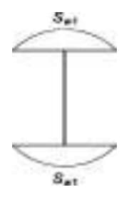
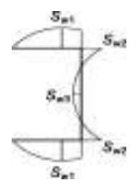
Fig. 1. Location of warping statical moment for W-, M-, S-, and HP-shapes.
Fig. 2. Location of warping statical moment for C- and MC-shapes.
Fig. 3. Location of Point A, B, and C for single angles.