N5.1 Quality Control
QC inspection tasks shall be performed by the fabricator’s or erector’s QCI, as applicable, in accordance with Sections N5.4, N5.6, and N5.7.
Tasks in Tables N5.4-1 through N5.4-3 and Tables N5.6-1 through N5.6-3 listed for QC are those inspections performed by the QCI to ensure that the work is performed in accordance with the construction documents.
For QC inspection, the applicable construction documents are the fabrication documents and the erection documents, and the applicable referenced specifications, codes, and standards.
User Note: The QCI need not refer to the design documents and project specifications. The Code of Standard Practice Section 4.2.1(a) requires the transfer of information from the contract documents (design documents and project specification) into accurate and complete fabrication and erection documents, allowing QC inspection to be based upon fabrication and erection documents alone.
N5.2 Quality Assurance
The QAI shall review the material test reports and certifications as listed in Section N3.2 for compliance with the construction documents.
QA inspection tasks shall be performed by the QAI in accordance with Sections N5.4, N5.6, and N5.7.
Tasks in Tables N5.4-1 through N5.4-3 and N5.6-1 through N5.6-3 listed for QA are those inspections performed by the QAI to ensure that the work is performed in accordance with the construction documents.
Concurrent with the submittal of such reports to the AHJ, EOR, or owner, the QA agency shall submit to the fabricator and erector the following:
(a) Inspection reports
- (b) NDT reports
| Inspection Tasks Prior to Welding | QC | QA |
|---|---|---|
| Welder qualification records and continuity records | P | O |
| WPS available | P | P |
| Manufacturer certifications for welding consumables available | P | P |
| Material identification (type/grade) | O | O |
| Welder identification system • Fabricator or erector, as applicable, shall maintain a system by which a welder who has welded a joint or member can be identified. • Die stamping of members subjected to fatigue shall be prohibited unless approved by the engineer of record. | O | O |
| Fit-up of groove welds (including joint geometry) • Joint preparations • Dimensions (alignment, root opening, root face, bevel) • Cleanliness (condition of steel surfaces) • Tacking (tack weld quality and location) • Backing type and fit (if applicable) | O | O |
| Fit-up of CJP groove welds of HSS T-, Y-, and K-connections with-out backing (including joint geometry) • Joint preparations • Dimensions (alignment, root opening, root face, bevel) • Cleanliness (condition of steel surfaces) • Tacking (tack weld quality and location) | P | O |
| Configuration and finish of access holes | O | O |
| Fit-up of fillet welds • Dimensions (alignment, gaps at root) • Cleanliness (condition of steel surfaces) • Tacking (tack weld quality and location) | O | O |
| Check welding equipment | O | − |
N5.3 Coordinated Inspection
When a task is noted to be performed by both QC and QA, it is permitted to coor- dinate the inspection function between the QCI and QAI so that the inspection functions are performed by only one party. When QA relies upon inspection func- tions performed by QC, the approval of the EOR and the AHJ is required.
N5.4 Inspection of Welding
Observation of welding operations and visual inspection of in-process and completed welds shall be the primary method to confirm that the materials, procedures, and workmanship are in conformance with the construction documents.
| Inspection Tasks During Welding | QC | QA |
|---|---|---|
| Control and handling of welding consumables • Packaging • Exposure control | O | O |
| No welding over cracked tack welds | O | O |
| Environmental conditions • Wind speed within limits • Precipitation and temperature | O | O |
| WPS followed • Settings on welding equipment • Travel speed • Selected welding materials • Shielding gas type/flow rate • Preheat applied • Interpass temperature maintained (min./max.) • Proper position (F, V, H, OH) | O | O |
| Welding techniques • Interpass and final cleaning • Each pass within profile limitations • Each pass meets quality requirements | O | O |
| Placement and installation of steel headed stud anchors | P | P |
User Note: The technique, workmanship, appearance, and quality of welded construction are addressed in Section M2.4.
As a minimum, welding inspection tasks shall be in accordance with Tables N5.4-1, N5.4-2, and N5.4-3. In these tables, the inspection tasks are as follows:
- (a) Observe (O): The inspector shall observe these items on a random basis. Operations need not be delayed pending these inspections.
- (b) Perform (P): These tasks shall be performed for each welded joint or member.
N5.5 Nondestructive Testing of Welded Joints
N5.5a Procedures
Ultrasonic testing (UT), magnetic particle testing (MT), penetrant testing (PT), and radiographic testing (RT), where required, shall be performed by QA in accordance with AWS D1.1/D1.1M.
User Note: The technique, workmanship, appearance, and quality of welded construction is addressed in Section M2.4.
| Inspection Tasks After Welding | QC | QA |
|---|---|---|
| Welds cleaned | O | O |
| Size, length, and location of welds | P | P |
| Welds meet visual acceptance criteria • Crack prohibition • Weld/base-metal fusion • Crater cross section • Weld profiles • Weld size • Undercut • Porosity | P | P |
| Arc strikes | P | P |
| k-area[a] | P | P |
| Weld access holes in rolled heavy shapes and built-up heavy shapes[b] | P | P |
| Backing removed and weld tabs removed (if required) | P | P |
| Repair activities | P | P |
| Document acceptance or rejection of welded joint or member[c] | P | P |
| No prohibited welds have been added without the approval of the engineer of record | O | O |
[a]When welding of doubler plates, continuity plates, or stiffeners has been performed in the k-area, visually inspect the web k-area for cracks within 3 in. (75 mm) of the weld.
N5.5b CJP Groove Weld NDT
For structures in risk category III or IV, as defined in ASCE/SEI 7, UT shall be performed by QA on all complete-joint-penetration (CJP) groove welds subjected to transversely applied tension loading in butt, T-, and corner joints, in material 5/16 in. (8 mm) thick or greater. For structures in risk category II, UT shall be performed by QA on 10% of CJP groove welds in butt, T-, and corner joints subjected to transversely applied tension loading, in materials 5/16 in. (8 mm) thick or greater.
User Note: For structures in risk category I, NDT of CJP groove welds is not required. For all structures in all risk categories, NDT of CJP groove welds in materials less than 5/16 in. (8 mm) thick is not required.
N5.5c Welded Joints Subjected to Fatigue
When required by Appendix 3, Table A-3.1, welded joints requiring weld soundness to be established by radiographic or ultrasonic inspection shall be tested by QA as prescribed. Reduction in the rate of UT is prohibited.
N5.5d Ultrasonic Testing Rejection Rate
The ultrasonic testing rejection rate shall be determined as the number of welds containing defects divided by the number of welds completed. Welds that contain acceptable discontinuities shall not be considered as having defects when the rejection rate is determined. For evaluating the rejection rate of continuous welds over 3 ft (1 m) in length where the effective throat is 1 in. (25 mm) or less, each 12 in. (300 mm) increment or fraction thereof shall be considered as one weld. For evaluating the rejection rate on continuous welds over 3 ft (1 m) in length where the effective throat is greater than 1 in. (25 mm), each 6 in. (150 mm) of length, or fraction thereof, shall be considered one weld.
N5.5e Reduction of Ultrasonic Testing Rate
For projects that contain 40 or fewer welds, there shall be no reduction in the ultrasonic testing rate. The rate of UT is permitted to be reduced if approved by the EOR and the AHJ. Where the initial rate of UT is 100%, the NDT rate for an individual welder or welding operator is permitted to be reduced to 25%, provided the rejection rate, the number of welds containing unacceptable defects divided by the number of welds completed, is demonstrated to be 5% or less of the welds tested for the welder or welding operator. A sampling of at least 40 completed welds shall be made for such reduced evaluation on each project.
N5.5f Increase in Ultrasonic Testing Rate
For structures in risk category II and higher (where the initial rate for UT is 10%) the NDT rate for an individual welder or welding operator shall be increased to 100% should the rejection rate (the number of welds containing unacceptable defects divided by the number of welds completed) exceed 5% of the welds tested for the welder or welding operator. A sampling of at least 20 completed welds on each project shall be made prior to implementing such an increase. If the rejection rate for the welder or welding operator falls to 5% or less on the basis of at least 40 completed welds, the rate of UT may be decreased to 10%.
N5.5g Documentation
All NDT performed shall be documented. For shop fabrication, the NDT report shall identify the tested weld by piece mark and location in the piece. For field work, the NDT report shall identify the tested weld by location in the structure, piece mark, and location in the piece.
When a weld is rejected on the basis of NDT, the NDT record shall indicate the location of the defect and the basis of rejection.
N5.6 Inspection of High-Strength Bolting
Observation of bolting operations shall be the primary method used to confirm that the materials, procedures, and workmanship incorporated in construction are in conformance with the construction documents and the provisions of the RCSC Specification.
| Inspection Tasks Prior to Bolting | QC | QA |
|---|---|---|
| Manufacturer’s certifications available for fastener materials | O | P |
| Fasteners marked in accordance with ASTM requirements | O | O |
| Correct fasteners selected for the joint detail (grade, type, bolt length if threads are to be excluded from shear plane) | O | O |
| Correct bolting procedure selected for joint detail | O | O |
| Connecting elements, including the appropriate faying surface condition and hole preparation, if specified, meet applicable requirements | O | O |
| Pre-installation verification testing by installation personnel observed and documented for fastener assemblies and methods used | P | O |
| Protected storage provided for bolts, nuts, washers, and other fastener components | O | O |
- (a) For snug-tight joints, pre-installation verification testing as specified in Table N5.6-1 and monitoring of the installation procedures as specified in Table N5.6-2 are not applicable. The QCI and QAI need not be present during the installation of fasteners in snug-tight joints.
- (b) For pretensioned joints and slip-critical joints, when the installer is using the turn-of-nut or combined method with matchmarking techniques, the direct-tension-indicator method, or the twist-off-type tension control bolt method, monitoring of bolt pretensioning procedures shall be as specified in Table N5.6-2. The QCI and QAI need not be present during the installation of fasteners when these methods are used by the installer.
- (c) For pretensioned joints and slip-critical joints, when the installer is using the turn-of-nut or combined method without matchmarking, or the calibrated wrench method, monitoring of bolt pretensioning procedures shall be as specified in Table N5.6-2. The QCI and QAI shall be engaged in their assigned inspec- tion duties during installation of fasteners when these methods are used by the installer.
As a minimum, bolting inspection tasks shall be in accordance with Tables N5.6-1, N5.6-2, and N5.6-3. In these tables, the inspection tasks are as follows:
- (a) Observe (O): The inspector shall observe these items on a random basis. Operations need not be delayed pending these inspections.
- (b) Perform (P): These tasks shall be performed for each bolted connection.
| Inspection Tasks During Bolting | QC | QA |
|---|---|---|
| Fastener assemblies placed in all holes, and washers and nuts are positioned as required | O | O |
| Joint brought to the snug-tight condition prior to the pretensioning operation | O | O |
| Fastener component not turned by the wrench prevented from rotating | O | O |
| Fasteners are pretensioned in accordance with the RCSC Specification, progressing systematically from the most rigid point toward the free edges | O | O |
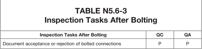
Figure description:
TABLE N5.6-3 Inspection Tasks After Bolting
Inspection Tasks After Bolting
| Inspection Tasks After Bolting | QC | QA |
|---|---|---|
| Document acceptance or rejection of bolted connections | P | P |
N5.7 Inspection of Galvanized Structural Steel Main Members
Exposed cut surfaces of galvanized structural steel main members and exposed corners of rectangular HSS shall be visually inspected for cracks subsequent to galvanizing. Cracks shall be repaired or the member shall be rejected.
User Note: It is normal practice for fabricated steel that requires hot-dip galvanizing to be delivered to the galvanizer and then shipped to the jobsite. As a result, inspection on site is common.
N5.8 Other Inspection Tasks
The fabricator’s QCI shall inspect the fabricated steel to verify compliance with the details shown on the fabrication documents.
User Note: This includes such items as the correct application of shop joint details at each connection.
The erector’s QCI shall inspect the erected steel frame to verify compliance with the field installed details shown on the erection documents.
User Note: This includes such items as braces, stiffeners, member locations, and correct application of field joint details at each connection.
The QAI shall be on the premises for inspection during the placement of anchor rods and other embedments supporting structural steel for compliance with the construction documents. As a minimum, the diameter, grade, type, and length of the anchor rod or embedded item, and the extent or depth of embedment into the concrete, shall be verified and documented prior to placement of concrete.
The QAI shall inspect the fabricated steel or erected steel frame, as applicable, to verify compliance with the details shown on the construction documents.
User Note: This includes such items as braces, stiffeners, member locations, and the correct application of joint details at each connection.
The acceptance or rejection of joint details and the correct application of joint details shall be documented.