HSS-to-HSS truss connections consist of one or more branch members directly welded to a chord that passes as a continuous element through the connection. Such connections shall be classified as follows:
TABLE K2.1
Available Strengths of Plate-to-Round HSS Connections
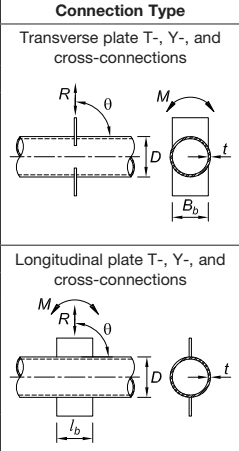
Figure description:
Plate-to-Round HSS Connection Types
1. Transverse plate T-, Y-, and cross-connections
- Description: Plates attached perpendicular to the round HSS axis.
- Key Parameters:
- : Connection strength/load
- : Moment
- : Angle of connection
- : HSS diameter
- : HSS wall thickness
- : Plate width
2. Longitudinal plate T-, Y-, and cross-connections
- Description: Plates attached parallel to the round HSS axis.
- Key Parameters:
- : Connection strength/load
- : Moment
- : Angle of connection
- : HSS diameter
- : HSS wall thickness
- : Plate length
Connection Available Strength
Plate Bending
Limit state: HSS local yielding
Plate axial load: In-plane: Out-of-plane:
| (K2-1a): |
|---|
| (K2-1b): |
| : |
Limit state: HSS plastification Plate axial load: (K2-2a) In-plane: (K2-2b) Out-of-plane: – (LRFD) (ASD)
TABLE K2.1A Limits of Applicability of Table K2.1
HSS wall slenderness: for T-connections under branch plate axial load or bending for cross-connections under branch plate axial load or bending Width ratio: for transverse branch plate connections Material strength: ksi (360 MPa) Ductility: Note: ASTM A500/A500M Grade C is acceptable.
- (a) When the punching load, , in a branch member is equilibrated by beam shear in the chord member, the connection shall be classified as a T-connection when the branch is perpendicular to the chord, and classified as a Y-connection otherwise.
- (b) When the punching load, , in a branch member is essentially equilibrated (within 20%) by loads in other branch member(s) on the same side of the connection, the connection shall be classified as a K-connection. The relevant gap is between the primary branch members whose loads equilibrate.
User Note: A K-connection with one branch perpendicular to the chord is often called an N-connection.
- (c) When the punching load, , is transmitted through the chord member and is equilibrated by branch member(s) on the opposite side, the connection shall be classified as a cross-connection.
- (d) When a connection has more than two primary branch members or branch members in more than one plane, the connection shall be classified as a general or multiplanar connection.
User Note: Limit states are not defined for general or multiplanar HSS-to-HSS truss connections.
When branch members transmit part of their load as K-connections and part of their load as T-, Y-, or cross-connections, the adequacy of the connections shall be determined by interpolation on the proportion of the available strength of each in total.
For trusses that are made with HSS that are connected by welding branch members to chord members, eccentricities within the limits of applicability are permitted without consideration of the resulting moments for the design of the connection.
K3.1 Definitions of Parameters
- eccentricity in a truss connection, positive being away from the branches, in. (mm)
- g = gap between toes of branch members in a gapped K-connection, neglecting the welds, in. (mm)
- , in. (mm)
- overlap length measured along the connecting face of the chord beneath the two branches, in. (mm)
- projected length of the overlapping branch on the chord, in. (mm)
- = gap ratio; the ratio of the gap between the branches of a gapped K-connection to the width of the chord for rectangular HSS
K3.2 Round HSS
The available strength of round HSS-to-HSS truss connections, within the limits in Table K3.1A, shall be taken as the lowest value obtained according to the limit states shown in Table K3.1.
K3.3 Rectangular HSS
The available strength, and , of rectangular HSS-to-HSS truss connections within the limits in Table K3.2A, shall be taken as the lowest value obtained according to limit states shown in Table K3.2 and Chapter J.
User Note: Outside the limits in Table K3.2A, the limit states of Chapter J are still applicable and the applicable limit states of Chapter K are not defined.
User Note: Maximum gap size in Table K3.2A will be controlled by the e/H limit. If the gap is large, treat as two Y-connections.
| Connection Type | Connection Available Axial Strength |
|---|---|
| General check for T-, Y-, cross-, and K-connections with gap, when Db (tens/comp) < (D - 2t) | Limit state: shear yielding (punching) Pn = 0.6FytDb (1+sinθ)/(2sin2θ) (K3-1) φ = 0.95 (LRFD) Ω = 1.58 (ASD) |
| T- and Y-connections | Limit state: chord plastification Pnsinθ = Fyt2 (3.1 + 15.6β2)γ0.2Qf (K3-2) φ = 0.90 (LRFD) Ω = 1.67 (ASD) |
| Cross-connections | Limit state: chord plastification Pnsinθ = Fyt2 (5.7 / (1-0.81β)) Qf (K3-3) φ = 0.90 (LRFD) Ω = 1.67 (ASD) |
| K-connections with gap or overlap | Limit state: chord plastification (Pnsinθ)compression branch = Fyt2 [2.0 + 11.33 (Db comp / D)] QgQf (K3-4) (Pnsinθ)tension branch = (Pnsinθ)compression branch (K3-5) φ = 0.90 (LRFD) Ω = 1.67 (ASD) |
| Functions | |
| Qg = γ0.2 [1 + (0.024γ1.2) / (exp((0.5g/t) - 1.33) + 1)] (K3-6) | |
| Note that exp(x) is equal to ex, where e = 2.71828 is the base of the natural logarithm. | |
| Connection eccentricity: | -0.55 ≤ e/D ≤ 0.25 for K-connections |
| Chord wall slenderness: | D/t ≤ 50 for T-, Y-, and K-connections |
| D/t ≤ 40 for cross-connections | |
| Branch wall slenderness: | D_b/t_b ≤ 50 for tension and compression branch |
| D_b/t_b ≤ 0.05E/F_yb for compression branch | |
| Width ratio: | 0.2 ≤ D_b/D ≤ 1.0 for T-, Y-, cross-, and overlapped K-connections |
| 0.4 ≤ D_b/D ≤ 1.0 for gapped K-connections | |
| Gap: | g ≥ t_b comp + t_b tens for gapped K-connections |
| Overlap: | 25% ≤ Ov ≤ 100% for overlapped K-connections |
| Branch thickness: | t_b overlapping ≤ t_b overlapped for branches in overlapped K-connections |
| Material strength: | F_y and F_yb ≤ 52 ksi (360 MPa) |
| Ductility strength: | F_y/F_u and F_yb/F_ub ≤ 0.8 Note: ASTM A500/A500M Grade C is acceptable. |
User Note: The available axial strength for rectangular HSS-to-HSS member connections, or , is obtained from Chapter J and the AISC Steel Construction Manual Part 9.