HSS-to-HSS moment connections are defined as connections that consist of one or two branch members that are directly welded to a continuous chord that passes through the connection, with the branch or branches loaded by bending moments.
A connection shall be classified as
- (a) A T-connection when there is one branch and it is perpendicular to the chord and as a Y-connection when there is one branch, but not perpendicular to the chord
- (b) A cross-connection when there is a branch on each (opposite) side of the chord
K4.1 Definitions of Parameters
plastic section modulus of branch about the axis of bending, in.
K4.2 Round HSS
The available strength of round HSS-to-HSS moment connections within the limits of Table K4.1A shall be taken as the lowest value of the applicable limit states shown in Table K4.1.
TABLE K3.2
Available Strengths of Rectangular HSS-to-HSS Truss Connections
Connection Type Connection Available Axial Strength
Gapped K-Connections
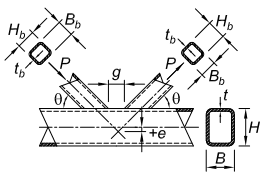
Figure description:
Technical diagram of a Gapped K-Connection involving rectangular hollow structural sections (HSS:
- Main Member (Chord: Specified by height (, width (, and wall thickness (.
- Branch Members: Two diagonal members with height (, width (, and wall thickness (, applied axial load (, and connection angle (.
- Connection Geometry:
- : Gap distance between the two branch members on the chord face.
- : Eccentricity, indicating the vertical offset between the branch axes intersection and the chord centerline.
Overlapped K-Connections
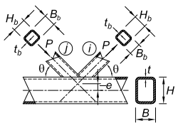
Figure description:
Key Information: Overlapped K-Connection
- Connection Type: Overlapped K-connection joining two diagonal branch members (labeled i and j to a main horizontal chord.
- Chord Dimensions:
- : Chord width
- : Chord height
- : Chord wall thickness
- Branch Dimensions (Members i & j:
- : Branch width
- : Branch height/depth
- : Branch wall thickness
- Geometric & Structural Parameters:
- : Angle between the branch and the chord.
- (Eccentricity: Vertical distance between the chord's longitudinal axis and the intersection point of the branches' axes.
- : Axial force applied to branch members.
- Configuration Detail: Branch i overlaps branch j at the junction on the chord surface.
Note that the force arrows shown for overlapped K-connections may be reversed; i and j control member identification.
Limit state: chord wall plastification, for all (K3-7) (LRFD) (ASD) Limit state: shear yielding (punching), when This limit state need not be checked for square branches. (K3-8) (LRFD) (ASD) Limit state: shear of chord side walls in the gap region Determine in accordance with Section G4. This limit state need not be checked for square chords. Limit state: local yielding of branch/branches due to uneven load distribution This limit state need not be checked for square branches or where . (K3-9) (LRFD) (ASD)
Limit state: local yielding of branch/branches due to uneven load distribution When (K3-10) When (K3-11) When (K3-12) (K3-13) (K3-14) Subscript refers to the overlapping branch. Subscript refers to the overlapped branch. (K3-15)
Functions
(K3-16) (K3-17)
| Connection eccentricity: | -0.55 ≤ e/H ≤ 0.25 for K-connections |
| Chord wall slenderness: | B/t and H/t ≤ 35 for gapped K-connections and T-, Y-, and cross-connections |
| B/t ≤ 30 for overlapped K-connections | |
| H/t ≤ 35 for overlapped K-connections | |
| Branch wall slenderness: | Bb/tb and Hb/tb ≤ 35 for tension branch |
| ≤ 1.25 √E/Fyb for compression branch of gapped K-, T-, Y-, and cross-connections | |
| ≤ 35 for compression branch of gapped K-, T-, Y-, and cross-connections | |
| ≤ 1.1 √E/Fyb for compression branch of overlapped K-connections | |
| Width ratio: | Bb/B and Hb/B ≥ 0.25 for T-, Y-, cross-, and overlapped K-connections |
| Aspect ratio: | 0.5 ≤ Hb/Bb ≤ 2.0 and 0.5 ≤ H/B ≤ 2.0 |
| Overlap: | 25% ≤ Ov ≤ 100% for overlapped K-connections |
| Branch width ratio: | Bbi/Bbj ≥ 0.75 for overlapped K-connections, where subscript i refers to the overlapping branch and subscript j refers to the overlapped branch |
| Branch thickness ratio: | tbi/tbj ≤ 1.0 for overlapped K-connections, where subscript i refers to the overlapping branch and subscript j refers to the overlapped branch |
| Material strength: | Fy and Fyb ≤ 52 ksi (360 MPa) |
| Ductility: | Fy/Fu and Fyb/Fub ≤ 0.8 Note: ASTM A500/A500M Grade C is acceptable. |
Additional Limits for Gapped K-Connections
| Width ratio: | Bb / B and Hb / B ≥ 0.1 + γ / 50 |
| βeff ≥ 0.35 | |
| Gap ratio: | ξ = g/B ≥ 0.5(1-βeff) |
| Gap: | g ≥ tb compression branch + tb tension branch |
| Branch size: | smaller Bb ≥ 0.63(larger Bb), if both branches are square |
| Connection Type | Connection Available Flexural Strength |
|---|---|
| Branch(es) under in-plane bending T-, Y-, and cross-connections [Diagram of in-plane bending connection: Shows a round HSS chord with a branch HSS welded to it at an angle, illustrating dimensions M, Db, tb, θ, t, D] | Limit state: chord plastification Mn-ip = 5.39Fyt20.5β (Db/sinθ) Qf (K4-1) φ = 0.90 (LRFD) Ω = 1.67 (ASD) |
| Limit state: shear yielding (punching), when Db < (D-2t) Mn-ip = 0.6FytDb2 ((1+3sinθ)/(4sin2θ)) (K4-2) φ = 0.95 (LRFD) Ω = 1.58 (ASD) | |
| Branch(es) under out-of-plane bending T-, Y-, and cross-connections [Diagram of out-of-plane bending connection: Shows a round HSS chord with a branch HSS welded perpendicular to it, illustrating dimensions M, Db, tb, t, D] | Limit state: chord plastification Mn-op = (Fyt2Db/sinθ) ((3.0)/(1-0.81β)) Qf (K4-3) φ = 0.90 (LRFD) Ω = 1.67 (ASD) |
| Limit state: shear yielding (punching), when Db < (D-2t) Mn-op = 0.6FytD2 ((3+sinθ)/(4sin2θ)) (K4-4) φ = 0.95 (LRFD) Ω = 1.58 (ASD) | |
| For T-, Y-, and cross-connections, with branch(es) under combined axial load, in-plane bend-ing, and out-of-plane bending, or any combination of these load effects Pr/Pc + (Mr-ip/Mc-ip)2 + Mr-op/Mc-op ≤ 1.0 (K4-5) Pr = required axial strength in branch using LRFD or ASD load combinations, kips (N) Mr-ip = required in-plane flexural strength in branch using LRFD or ASD load combinations, kip-in. (N-mm) Mr-op = required out-of-plane flexural strength in branch using LRFD or ASD load combinations, kip-in. (N-mm) Pc = available axial strength obtained from Table K3.1, kips (N) Mc-ip = available strength for in-plane bending, kip-in. (N-mm) Mc-op = available strength for out-of-plane bending, kip-in. (N-mm) | |
| Chord wall slenderness: | D/t ≤ 50 for T- and Y-connections D/t ≤ 40 for cross-connections |
| Branch wall slenderness: | Db/tb ≤ 50 0.05E/Fyb ≤ Db/tb |
| Width ratio: | 0.2 < Db/D ≤ 1.0 |
| Material strength: | Fy and Fyb ≤ 52 ksi (360 MPa) |
| Ductility: | Fy/Fu and Fyb/Fub ≤ 0.8 Note: ASTM A500/A500M Grade C is acceptable. |
K4.3 Rectangular HSS
The available strength, and , of rectangular HSS-to-HSS moment connections within the limits in Table K4.2A shall be taken as the lowest value obtained according to limit states shown in Table K4.2 and Chapter J.
User Note: Outside the limits in Table K4.2A, the limit states of Chapter J are still applicable and the applicable limit states of Chapter K are not defined.