This Appendix provides best practices for locking features.
B.2 Background and Introduction
Threaded fasteners are often used in dynamic environments, including vibration, shock, thermal cycles, and pressure cycles. As a result, threaded fasteners often experience dynamic tensile, shear, and moment loads. A properly designed preloaded joint will have sufficient preload (taking into account torque-tension uncertainty, embedment, etc.) such that the dynamic loads have little or no effect on joint integrity. However, if unexpected dynamic loads or temperature cycles are encountered that are sufficient to cause cyclic slip (localized or complete; see Pai and Hess (2002)) at the fastener thread or bearing surfaces, then fastener loosening, preload loss, and component/fastener loss can occur.
The friction at fastener thread and bearing surfaces in a properly designed preloaded joint is the mechanism that prevents slip in a preloaded joint. This friction is proportional to preload. As a result, preload is often referred to as a primary locking feature in a preloaded joint.
In an effort to eliminate or reduce loosening and possible failure in the event of unexpected dynamic loads, temperature excursions, or design errors or to provide locking in fasteners without preload (e.g., fasteners in some electrical applications), additional locking mechanisms or features are often utilized or required. These include the following: (a) mechanical locking devices such as cotter pins and safety wire; (b) prevailing torque devices such as fasteners with a deformed portion of threads or a polymer patch; (c) adhesives such as anaerobic adhesive; and (d) free spinning locking devices such as fasteners with serrated bearing surfaces or lock washers. Such devices or features are often considered secondary locking features when used in a preloaded joint with preload providing primary locking.
Experience has shown these locking features have the following characteristics:
-
a. Mechanical locking features such as cotter pins and safety wire allow some rotation until abutment that results in some loss of preload.
-
b. In severe vibration and shock environments, the main feature of prevailing torque locking devices is to prevent complete separation and loss of fasteners (i.e., provide foreign object debris protection), not to maintain preload.
-
c. With adequate cure, adhesives perform comparatively well in maintaining preload even in severe vibration and shock environments.
-
d. Free spinning locking devices such as fasteners with serrated bearing surfaces perform comparatively well, but their function is dependent on preload. Because of this dependence on preload, free spinning locking devices cannot be used as a secondary locking feature if preload is used for primary locking. Loss of preload removes both locking features. In addition, serrations can damage joint bearing surfaces. Free spinning split lock and tooth lock washers provide minimal, if any, locking.
-
e. Figure 29, Locking Feature Selection Flowchart, provides basic guidance for locking feature selection. The following sections of this appendix provide more information and guidance on locking features and devices, including appropriate specifications, best practices, limitations, and installation.
B.3 Best Practices for Mechanical Locking Features
Mechanical locking features include, but are not limited to, cotter pins, safety wire, and safety cable. These parts are covered by industry standards such as NASM 33540.
Mechanical locking features provide a reliable locking method for joints but come with drawbacks and design details that must be considered. Most mechanical locking features require additional parts that may increase the design’s complexity and weight. Sharp edge hazards from mechanical locking features are not acceptable for designs in crew translation paths for crewed spaceflight vehicles or crew actuated joints (EVA requirements are outlined in JSC-28918, EVA Design Requirements and Considerations). Mechanical locking features posing sharp edge hazards may be mitigated using encapsulation methods with room-temperature vulcanizing silicones or epoxy; however, materials must be compatible with their use environment.
Mechanical locking features such as cotter pins and safety wire allow some rotation until abutment. This can lead to loss of preload. As an example, Light (1983) presents data showing 30-percent loss of preload under severe vibration conditions from this rotation.
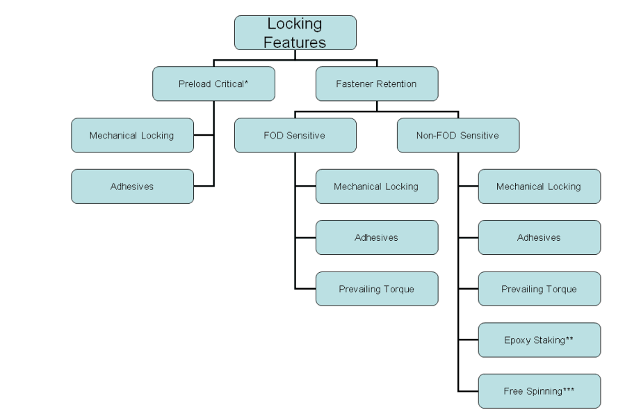
Figure description:
Locking Features Flowchart Entities and Categories:
- Preload Critical*
- Mechanical Locking
- Adhesives
- Fastener Retention
- FOD Sensitive
- Mechanical Locking
- Adhesives
- Prevailing Torque
- Non-FOD Sensitive
- Mechanical Locking
- Adhesives
- Prevailing Torque
- Epoxy Staking**
- Free Spinning***
- FOD Sensitive
*Mechanical and adhesive locking features are the best options for preload-critical joints but should not be relied upon to maintain preload. Proper joint design is necessary to maintain preload in dynamic environments.
**Epoxy staking is most often used for fasteners no larger than #8 or M4. Requirements for staking of nonstructural fastening systems used on electrical printed wiring assemblies (PWA) are found in NASA-STD-8739.1. Guidelines for the use of epoxy staking are given in Appendix B.5.1.
***Locking features such as jam nuts may not meet the requirements in section 4.6 if they require preload to function effectively, or if a change in preload could compromise the locking performance.
Figure 29—Locking Feature Selection FlowchartB.4 Best Practices for Prevailing Torque Locking Features B.4.1 General
-
a. Compared to fasteners with no secondary locking feature, prevailing torque locking devices can prevent complete separation of a fastening system after preload is lost. Due to the interference introduced by prevailing torque locking devices, they will help reduce the rate at which preload is lost.
-
b. In severe vibration and shock environments, the main feature of prevailing torque locking devices is to prevent complete separation and loss of fasteners, not to maintain preload.
-
c. Where inserts will be reused, the locking feature should be on the more easily inspected and replaced externally threaded fastener. To minimize the potential for damage due to installation, the mating components should be selected to be compatible with each other.
B.4.2 Prevailing Torque Locking Devices B.4.2.1 Self-Locking Nuts
-
a. Self-locking nuts are nuts with a locking feature resulting from a deformed (e.g., to an elliptical shape), undersized portion of the threads or incorporating nonmetallic (polymeric) insert. The locking feature can also be provided by a non-metallic (such as nylon) element that protrudes from the nut internal threads. The locking feature can be verified by measuring running torque.
-
b. NASM 25027, Nut, Self-Locking, 250 Degrees F, 450 Degrees F, and 800 Degrees F; and NAS 3350, Nuts, Self-Locking, 450 Degrees F and 800 Degrees F, High Quality, are the performance specifications for self-locking nuts. These include maximum locking (prevailing) torque and minimum breakaway torque values. NASM 25027 covers metal nuts with non-metal and metal locking features. NAS 3350 covers nuts with all all-metal locking features.
-
c. The unseated cycle life of 15 cycles required for qualification by NASM 25027 and NAS 3350 should not be assumed for seated cycle life. No seated cycle life requirement exists. Seating the bolt will affect the locking torque and the number of locking cycles. The extent of the effect is dependent upon materials of construction, lubrication, and preload.
-
d. Usage limitations are provided in NASM 33588, Nut, Self-Locking, Aircraft, Reliability and Maintainability Usage Requirements For. Examples include the following:
-
(1) Not using self-locking nuts on an axis of rotation.
-
(2) Ensuring external thread extends at least two threads through nut.
-
(3) Not using silver-plated nuts with silver-plated bolts. Temperature limitations for nonmetallic locking features are provided in NASM 25027.
-
e. Examples of self-locking nuts are as follows:
-
(1) NAS 1291, Nut, Self-Locking, Hexagon – Low Height, Light Weight.
-
(2) NASM 21043, Nut, Self-Locking, 800 Degrees F, Reduced Hexagon, Reduced Height, Ring Base, Corrosion Resistant Steel.
-
(3) NASM 21045, Nut, Self-Locking Hexagon – Regular Height, 450 Degrees F, 125 ksi Ftu.
-
(4) NASM 21046, Nut, Self-Locking, Hexagon - Regular Height, 800 Degrees F, 125 ksi Ftu.
B.4.2.2 Self-Locking Nut Plates
- a. Self-locking nut plates use the same locking features as self-locking nuts.
- b. Examples of self-locking nut plates are NAS 1068, Nut, Self-Locking Plate, Two Lug, Low Height, C'bored, Floating, Reduced Rivet Spacing; and NAS 1773, Nut, Self-Locking, Plate, Two Lug, Low Height, C´Bored, Floating, 160 ksi, 450 Degrees F, 800 Degrees F; and NAS 1774, Nut, Self-Locking, Plate, One Lug, Low Height, C´Bored, Floating, 160 ksi, 450 Degrees F, 800 Degrees F.
B.4.2.3 Self-Locking Bolts with Nonmetallic Locking Feature
-
a. Self-locking bolts are bolts with a locking feature resulting from a polymer plug, pellet, strip, or patch.
-
b. Vibra-TITE® is pre-applied and dried before installation with no bonding between mating threads and is therefore not considered an adhesive. Performance characteristics per MIL-DTL-18240, Fastener Element, Self-Locking, Threaded Fastener, 250 °F Maximum, could be used.
-
c. MIL-DTL-18240 is the specification for locking bolts up to 121°C (250°F) (temperature limit due to polymer locking material). This specification includes maximum and minimum running torque values.
-
d. A seated cycle life of five cycles is required for qualification by MIL-DTL-18240.
-
e. Usage limitations are given in NAS 15981, Fasteners, Externally Threaded, Self- Locking Design and Usage Limitations, and are similar to those given for locknuts in NASM 33588.
-
f. Examples of fasteners that can be purchased as self-locking are as follows:
-
(1) NAS 6703–NAS 6720, Bolt, Tension, Hex Head, Close Tolerance, A286 CRES, Long Thread, Reduced Major Thread Diameter, Self-Locking and Nonlocking, 160 ksi Ftu.
-
(2) NAS 8100–NAS 8106, Screw, Pan Head, Cruciform Recess, A-286 CRES, Full Thread, Self-Locking and Non Locking.
-
(3) NAS 1189, Screw, Self-Locking, Flat 100 Degree Head, Cruciform and Offset Cruciform Recess, Full Thread.
-
(4) NAS 1351, Screw, Cap, Socket Head, Undrilled and Drilled, Plain and Self- Locking, Alloy Steel, Corrosion-Resistant Steel and Heat-Resistant Steel, UNRF-3A.
B.4.2.4 Self-Locking Helical-Coil Inserts
- a. Self-locking helical-coil inserts are coils of wire (e.g., diamond-shaped wire). They are installed in a tapped parent metal hole with a special tool and are slightly oversized to create a frictional interlocking. The locking feature is provided by a deformed or undersized portion of the coil (e.g., hex shape for one thread) that creates a running torque.
- b. NASM 8846, Inserts, Screw-Thread, Helical Coil, is the specification for self-locking helical coils. This includes maximum locking (prevailing) torque and minimum breakaway torque values.
- c. The unseated cycle life of 15 cycles required for qualification by NASM 8846 should not be assumed for seated cycle life. No seated cycle life requirement exists. Seating the bolt will affect the locking torque and the number of locking cycles. The extent of the effect is dependent upon materials of construction, lubrication, and preload.
- d. HeliCoil® Technical Bulletin 68-2, provides comprehensive data on pullout strength for a range of available insert lengths and parent material shear strength.
- e. It is common practice to “wet install” helical-coils in aluminum structure to prevent galvanic corrosion between a corrosion-resistant steel (CRES) insert and an aluminum structure. Primers such as those conforming to MIL-PRF-23377, Primer Coatings: Epoxy, High-Solids, should be applied to the insert/base metal interface. Excess primer may migrate to areas contacting the installed fastener and affect torque.
- f. In general, helical coils are easier to replace than key locked inserts. However, if not installed correctly, helical coils have the potential to back out when subjected to high vibrations.
B.4.2.5 Self-Locking Key Locked-In Inserts
-
a. Key locked-in inserts have integrally assembled keys on the outer diameter that stake (i.e., mechanically lock) the inserts inside a parent metal hole. The locking feature in a self- locking key locked-in insert is a deformed or undersized portion of the internal threads that creates a running torque.
-
b. MIL-I-45914, Insert, Screw Thread – Locked In, Key Locked, General Specification For, is the specification for key locked-in inserts.
-
c. The unseated cycle life of 15 cycles required for qualification by MIL-I-45914 should not be assumed for seated cycle life. No seated cycle life requirement exists. Seating the bolt will affect the locking torque and the number of locking cycles. The extent of the effect is dependent upon materials of construction, lubrication, and preload.
-
d. Heavy-duty and extra-heavy-duty key locked-in inserts provide more pullout resistance than thin-wall locked-in inserts and helical-coil inserts of the same length. MIL-I-45914 provides data on pullout required for qualification.
-
e. Key locked-in inserts are solid walled so that application of corrosion prevention primer is not as problematic as with helical-coil inserts.
-
f. Typical examples of key locked-in inserts are MS 51830, Insert, Screw - Thread, Locked in, Key-Locked, Miniature and Lightweight Insert, Screw - Thread, Locked in, Key- Locked, Miniature and Lightweight; MS 51831, Insert, Screw-Thread, Locked in, Key Locked, Heavy Duty and MS 51832, Insert, Screw-Thread, Locked In, Key-Locked, Extra Heavy Duty.
B.4.2.6 Self-Locking Thin-Wall, Locked-In Inserts
- a. Thin-wall, locked-in inserts are solid inserts that have a cylindrical shoulder at the top that is swaged into the parent metal with a special swaging tool. Swaging locks the insert into the hole and inhibits torque-out. The locking feature in self-locking thin-wall locked-in inserts is a deformed or undersized portion of the internal threads that creates a running torque on the fastener.
- b. MIL-I-45932, Insert, Screw Thread, Thin Wall, Locked In, General Specification For, is the specification for thin-wall locked-in inserts.
- c. The unseated cycle life of 15 cycles required for qualification by MIL-I-45932 should not be assumed for seated cycle life. No seated cycle life requirement exists. Seating the bolt will affect the locking torque and the number of locking cycles. The extent of the effect is dependent upon materials of construction, lubrication, and preload.
- d. Thin-wall inserts are useful in joints that require less edge distance compared to key locked-in inserts that require larger edge distance to prevent shear tear-out.
B.4.3 Inspect
- a. Parts are to be inspected. (See section 4.8.5.)
- b. Prevailing torque locking devices are generally used “as-received” from manufacturing. Wipe away any visible loose particles and contaminants but do not clean with solvents.
B.4.4 Installation and Verification
- a. Verify the prevailing torque locking device meets the appropriate specification, such as:
- (1) NASM 25027 and NAS 3350 for self-locking nuts and nut plates.
- (2) MIL-DTL-18240 for self-locking bolts.
- (3) NASM 8846 for self-locking helical-coil inserts.
- (4) MIL-I-45914 for self-locking key locked-in inserts.
- (5) MIL-I-45932 for self-locking thin-wall locked-in inserts.
- b. Finger assemble up to locking feature.
- c. Assemble two full turns further.
- d. Once locking feature is fully engaged, measure breakaway torque (torque to start motion in the on or off direction) and running torque.
- e. Should have at least one full turn left before fastener starts to seat.
- f. Verify measured torque (either breakaway or prevailing) is greater than the minimum breakaway torque required in the appropriate qualification specification.
- g. If both measured torques are within specification, then seat and tighten fastener to tightening torque, which is the sum of the preload torque required for desired preload plus the running torque.
- h. Record the applied torque, preload torque, running torque, locking device part number, and lot number.
B.5 Best Practices for Adhesive Locking Features B.5.1 Adhesives
-
a. Anaerobic
-
(1) Anaerobic adhesives (e.g., Loctite® ) are single component thread-locking compounds that cure in the absence of air. They are applied to the threads of a fastener just prior to installation and then cure in place between the mating threads. The locking feature results from filling the clearance between mating threads and preventing relative slip.
-
(2) MIL-S-22473, Sealing, Locking, and Retaining Compounds: (Single Component); MIL-S-46163, Sealing, Lubricating and Wicking Compounds: Thread-Locking, Anaerobic, Single-Component; and ASTM D5363, Standard Specification for Anaerobic Single-Component Adhesives (AN). However, MIL- S-22473 and MIL-S-46163 have been cancelled, so ASTM D5363 should be used.
-
(3) Detailed process steps should be followed including surface preparation, cleaning, and primer application.
-
(4) Typical design goals include selecting adhesive such that the break-loose torque is equal to or greater than the installation torque, and to meet prevailing torque device specification requirements when repairing worn-out, prevailing-torque locking features.
-
(5) Examples of anaerobic adhesives include Loctite® 222, removable grade for up to 6.35-mm (0.25-in) screws; Loctite® 242, removable grade for up to 19.05-mm (0.75-in) bolts; and Loctite® 262, permanent grade for up to 19.05-mm (0.75-in) bolts.
-
(6) Caution: When using anaerobic adhesives in blind holes, if adhesive is applied to the fastener or upper hole threads, entrapment of air in the hole and threads may prevent proper cure or push the adhesive out of the threads, leaving insufficient adhesive for locking. As a mitigation, some adhesive suppliers are recommending to only apply adhesive in the bottom of the blind hole. A development test may be necessary to ensure the resultant breakaway strength meets the desired minimum.
b. Epoxy and Staking Compounds
-
(1) These materials are used by applying a small amount of the compound onto both the fastener (usually the head) and the surrounding structure such that when cured, the adhesive bond to both fastener and structure prevents rotation of (stakes) the fastener. This method is often used in electronic assemblies where a lost fastener is captive within the assembly and cannot adversely affect the function of other components. Requirements for staking of nonstructural fastening systems used on electrical printed wiring assembles (PWA) are found in NASA-STD-8739.1. Staking methods are also sometimes used to secure fine- adjustment screws in position. Since adhesives are most susceptible to failure in peel, staking is considered a low-reliability locking feature. Epoxy and staking compounds are typically two-part materials requiring mixing before use.
-
(2) Detailed process steps should be followed, including surface preparation and cleaning, mixing components of compound, and application.
-
(3) Epoxy and staking compounds used in sensitive applications such as fluid wetted components, optical systems, and some external spacecraft surfaces can result in system contamination and performance degradation. Use of these materials should be considered for system-level contamination effects during design.
c. Other
- (1) Polyurethanes such as Arathane® and Solithane® that cure with or without residual oxygen remain gummy when cured and, in some instances, have been found to be effective even with residual lubricant on threads (HST-TR-010334, 2008).
- (2) Compounds such as Vibra-TITE® that are pre-applied and dried without curing before installation and with no bonding between mating threads are not considered adhesives and should not be used in safety-critical applications.
B.5.2 Process Validation
-
a. Acquire test verification specimens, as follows:
-
(1) Obtain at least five representative or witness fastener specimens (e.g., bolts, nuts, inserts, washers) of the same material, size, finish, part number, and lot number as used in intended application.
-
(2) Obtain representative clamped components of the same materials, finishes, clamping thickness, hole size, and tolerances. Parts of smaller size than clamped component in application are acceptable as long as the stiffness is comparable (e.g., cylinders).
-
(3) Record part and lot numbers of specimens and description of clamped components.
-
b. Inspect and clean (see Appendices B.5.3 and B.5.4), as follows:
-
(1) Visually inspect and verify that fastener components (e.g., bolts, nuts, washers, inserts, etc.) are free of damage. Discard damaged components.
-
(2) Clean external threads and internal threads but not the bearing surfaces of the fastener specimens (e.g., bolt, nut, and washers) in the same manner as is used in the intended application (e.g., using cloth, wipes, or swabs dampened with appropriate solvent such as acetone or methyl ethyl ketone (MEK)). If bearing surfaces must be cleaned, bearing surface lubrication may be necessary to prevent galling.
-
(3) Inspect and verify that the cleaned internal and external threads of test verification specimens are dry and free of residue, loose particles, and contamination as in intended application.
c. Prime, as follows:
- (1) For epoxy staking applications, apply one coat of primer to bonding surfaces.
- (2) For anaerobic adhesive applications, apply one coat of primer (e.g., Loctite® Primer, grade T or N) to the internal threads and external threads of the specimens as in intended application.
- (3) Apply primer by spray, brush, or swab and allow primer to dry for 15 minutes minimum or up to 5 days maximum, as in intended application.
- (4) Record primer part number (or grade), lot number, expiration date, and application date and time.
d. Apply adhesive, torque, and cure, as follows:
- (1) Prepare adhesive as specified by manufacturer (e.g., for epoxy adhesive, mix resin and hardener; for anaerobic adhesive, shake bottle).
- (2) Apply adhesive to both external and internal threads, 360 degrees around and over the complete thread engagement area, as in application.
- (3) Assemble representative fastener specimens and clamped components to torque specified in application.
- (4) Record adhesive part number (or grade), lot number, expiration date, and application date and time.
- (5) Allow to cure for cure time (e.g., 24 or 48 hours) specified in application.
e. Validation test, as follows:
- (1) Measure and record break loose torque (off direction) for each specimen.
- (2) Measure and record removal running torque for each specimen.
- (3) Depending upon design goal, (a) verify that the measured break loose torque (off direction) is greater than or equal to the installation torque; or (b) verify the running torque meets prevailing torque device specification requirements.
- (4) Verify adhesive has fully cured by inspection.
B.5.3 Inspect
- a. Parts are to be inspected. (See section 4.8.5.)
- b. Discard damaged components.
B.5.4 Clean
- a. Clean external threads and internal threads but not the bearing surfaces of the fastener specimens (e.g., bolt, nut, and washers) in the same manner as is used in the intended application (e.g., using cloth, wipes, or swabs dampened with appropriate solvent, such as acetone or MEK). If bearing surfaces must be cleaned, bearing surface lubrication may be necessary to prevent galling.
- b. Inspect and verify that the cleaned threads are dry and free of residue, loose particles, or contamination.
B.5.5 Prime (for anaerobic adhesives only)
- a. Use primer on inactive metals (e.g., aluminum, stainless steel, titanium, anodized, cadmium plated, and zinc plated).
- b. Apply one coat of primer to both the internal and external threads by spray, brush, or swab.
- c. Allow primer to dry for 15 minutes minimum.
- d. Primed parts may be stored for up to 5 days maximum in sealed plastic bags. If not used within 5 days, re-clean and re-prime parts.
- e. Record primer part number (or grade), lot number, expiration date, and application date and time.
B.5.6 Installation
-
a. Verify adhesive is within shelf life.
-
b. Prepare adhesive as specified by manufacturer (e.g., for epoxy adhesive, mix resin and hardener; for anaerobic adhesive, shake bottle).
-
c. Apply adhesive to internal and external threads, 360 degrees around and over the complete thread engagement area for blind holes. Apply adhesive to external threads, 360 degrees around and over the complete thread engagement area for through-hole assemblies. Ensure adhesive does not contact bearing surfaces.
-
d. Assemble within 5 minutes to specified torque.
-
e. Wipe excess adhesive from parts.
-
f. Record adhesive part number (or grade), lot number, expiration date, and application date and time.
-
g. Allow to cure for cure time (e.g., 24 or 48 hours) specified by manufacturer or engineering.
B.5.7 Verification
- a. Verify by using processes outlined in the process validation section (see Appendix B.5.2) using a coupon method.
- b. Five samples/coupons per configuration are required and need to be verified for each locking compound batch and technician.
- c. Inspect adhesive to ensure full cure.
B.5.8 General
- a. Cleaning and adhesives alter nut factor as follows:
- (1) Cleaning process removes residual lubricant from components (e.g., bolts, nuts, inserts, washers, etc.). Either be extremely careful not to remove residual lubricant from bearing surfaces or use lubricant between bearing surfaces of similar material (e.g., stainless steel bolt head and washer) to prevent galling.
- (2) Use the same cleaning, priming, adhesive application, and bearing surface treatment in the intended application as in the torque-tension tests used to obtain nut factor if preload is determined by torque measurement.
- b. Inadequate cleaning and priming of threads can lead to poor locking performance of adhesives.
- c. With adequate cleaning and priming of threads, adhesives can prevent loosening and maintain preload better than prevailing torque locking devices and mechanical locking devices in severe vibration and shock environments.
- d. Although adhesives are an appealing locking feature when an original prevailing torque locking feature has worn out, they are not a simple “quick fix.” The detailed process and verification steps of Appendix B.5 should be followed.
B.6 Best Practices for Free Spinning
- a. The mechanism of locking for free spinning locking devices is dependent on preload. Because of this dependence on preload, free spinning locking devices cannot be used as a secondary locking feature if preload is used for primary locking.
- b. Free-spinning locking devices with serrated bearing surfaces perform well compared to other locking devices; however, their function is dependent on preload (see above).
- c. Free-spinning locking devices with serrated bearing surfaces can damage joint bearing surfaces that can lead to crack formation and fatigue failure.
- d. Free spinning split lock washers provide minimal, if any, locking. Air Force-Navy Aeronautical Design (AND) 10476 standard, Washer – Limitations on Usage of Lock, limits the use of lock washers to situations when other locking features cannot be used and when loosening would not endanger the safety of structure or personnel.
- e. Split lock washers should not be used for secondary locking features.