4.2.1 Factor of Safety
[TFSR 2] Threaded fastening system hardware shall be designed using the structural factors of safety specified by the program or project for general structural design.
An example is NASA-STD-5001, Structural Design and Test Factors of Safety for Spaceflight Hardware.
[Rationale: Factors of safety are levied to provide margin between predicted service loads and the material strength.]
Factors of safety are applicable to limit load. A yield factor of safety, FSy , is applied in the assessment of yield strength, and an ultimate factor of safety, FSu , is applied in the assessment of ultimate strength. Factors of safety do not apply to fastener preload or changes in preload as a result of thermo-elastic deformation local to the fastening system hardware (for example, coefficient of thermal expansion mismatch between the bolt and joint).
4.2.2 Fitting Factor
[TFSR 3] Threaded fastening system hardware shall be designed using a fitting factor (FF).
[Rationale: A fitting factor is included in the strength and separation analysis of each part of the threaded fastening system to account for uncertainties in load paths and stresses.]
The factor of safety is multiplied by the fitting factor and typically applied to the tension and shear components, but not the preload, for fastened joints with multiple bolt locations. An example is shown in Eq. 15.
For purposes of analysis, joint members integral to a larger structural member are considered part of the threaded fastening system up to the point where their section properties become typical of the structural member away from the threaded fastening system.
Ultimate strength analysis of threaded fastening systems should include a fitting factor of at least 1.15 as a multiplier of the required ultimate factor of safety. The selection of a fitting factor for ultimate strength analysis should be strongly influenced by whether there is enough ductility in the critical failure mode to ensure load sharing between fasteners before any one fastening system fails. For example, consider a shear joint with metal joint members: Shear failure of a fastener can have little associated plastic deformation, whereas bearing failure of the joint member typically has considerable plastic deformation. Uneven load sharing can be the result of oversized bolt holes; but even if the bolts are in interference-fit holes, loads may not distribute evenly. If the margin of safety on bearing is lower than the margin of safety for bolt shear (referred to as a bearing-critical joint), shear loads will distribute more evenly between bolts
before the highest-loaded bolt fails. A shear-critical joint typically warrants a larger fitting factor.
Yield strength analysis of threaded fastening systems whose performance is particularly sensitive to local yielding should include a fitting factor of at least 1.15 as a multiplier of the required yield factor of safety.
In threaded fastening systems where there is clearance between the fasteners and the bearing surfaces, there is a likelihood that some fasteners may not share the load equally; and some fasteners may be unloaded. The selection of the fitting factor or the prediction of load sharing should reflect the expected clearances between the fasteners and the bearing surfaces and the stiffness of the fastened joint members.
The value of the fitting factor may be reduced when there is less uncertainty in the load paths and stresses or there is little sensitivity to those uncertainties in the analysis of threaded fastening systems. A fitting factor of 1.0 may be adequate in the strength analysis of fastened joints when at least one of the following applies:
- The threaded fastening system’s strength is verified in an ultimate load test in which actual load paths and stresses are simulated in the joint and surrounding structure; or
- The threaded fastening system’s load paths and stresses have been determined with detailed finite element analysis using modeling practices that have been correlated with tests of similar threaded fastening systems in which actual load paths and stresses were simulated and measured; or
- The threaded fastening system contains redundant load paths (e.g., multiple fasteners) and sufficient ductility to allow the load to redistribute before failure.
Separation analysis of joints that are separation-critical should include a fitting factor of at least 1.15 as a multiplier of the required separation factor of safety.
A fitting factor of 1.0 may be adequate in the strength analysis of fastened joints when at least one of the following applies:
- The threaded fastening system is not separation-critical; or
- The threaded fastening system is separation-critical but the joint’s functionality is verified in a test to limit load or greater on hardware representative of the flight design in which actual load paths and stresses are simulated in the joint and surrounding structure; or
- The threaded fastening system is separation-critical but the joint’s load paths and stresses have been determined with detailed finite element analysis using modeling
practices that have been correlated with tests of similar threaded fastening systems in which actual load paths and stresses were simulated and measured.
4.2.3 Separation Factor of Safety
[TFSR 4] Threaded fastening system hardware shall be designed using the separation factor of safety (FSsep ) specified by Figure 1, Logic Flow for Minimum Separation Factor of Safety.
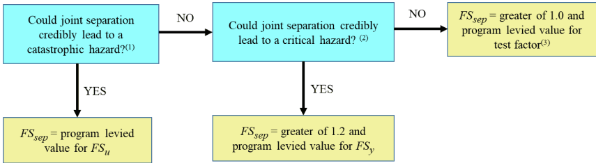
Figure description:
Logic Flow for Minimum Separation Factor of Safety (
Decision Points (Blue Blocks:
- Could joint separation credibly lead to a catastrophic hazard?⁽¹⁾
- YES: = program levied value for
- NO: Proceed to next decision point.
- Could joint separation credibly lead to a critical hazard?⁽²⁾
- YES: = greater of 1.2 and program levied value for
- NO: = greater of 1.0 and program levied value for test factor⁽³⁾
Key Entities:
- : Minimum Separation Factor of Safety.
- Catastrophic hazard: Highest tier of hazard indicated.
- Critical hazard: Second tier of hazard indicated.
- : Program levied value used if a catastrophic hazard is possible.
- : Program levied value used if a critical hazard is possible.
- Test factor: Value used if no catastrophic or critical hazards are identified.
(1)A hazard that could result in a mishap causing fatal injury to personnel, and/or loss of one or more major elements of the flight vehicle or ground facility. A condition that may cause death or permanently disabling injury, major system or facility destruction on the ground, or loss of crew, major systems, or vehicle during the mission.
(2)A condition that may cause severe injury or occupational illness, or major property damage to facilities, systems, or flight hardware.
(3) If testing, such as proof or acceptance, is to be performed at higher than limit load, the factor should be increased to envelope test conditions to preclude separation during test.
Figure 1—Logic Flow for Minimum Separation Factor of Safety
[Rationale: A factor of safety greater than 1.0 applied to separation analysis provides additional margin between predicted service loads and the nominal or minimum expected preload in a fastened joint.]
A separation-critical joint is a joint that fails to function as required if separated. Examples of separation-critical joints include, but are not limited to, joints that must maintain contact to enable proper function of a system (e.g., thermal, electrical, fluid) or joints whose dynamic stiffness is reduced due to separation.
Primary structure with joints classified as “non-separation critical” and FSsep = 1.0 could separate when tested above limit load (e.g., qualification tests using 1.25 x limit load) producing alignment/performance issues, a shift in dynamic response, or both. In these scenarios, if the consequence of joint separation during testing can lead to a failure to satisfy test success criteria, then consider selecting a greater value for FSsep to produce a positive margin of safety on separation under test loads and environments, as well as flight loads and environments.