To avoid having to reject test pieces where the position of the fracture does not comply with the conditions of 11.1, the following method may be used, by agreement:
- a) before the test, sub-divide the original gauge length ( ) into equal parts;
b) after the test, use the symbol X to denote the gauge mark on the shorter piece and the symbol Y to denote it on the longer piece, the subdivision of which is at the same distance from the fracture as mark X.
If is the number of intervals between X and Y, the elongation after fracture is determined as follows:
- if is an even number [see figure G.1 a)], measure the distance between X and Y and the distance from Y to the graduation mark Z located at
intervals beyond Y;
calculate the percentage elongation after fracture using the equation
- if is an odd number [figure G.1 b)], measure the distance between X and Y and the distance from Y to the graduation marks and located respectively at
and intervals beyond Y;
calculate the percentage elongation after fracture using the equation
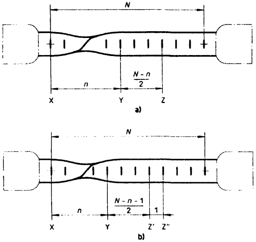
Figure description:
The image shows technical diagrams (labeled a and b illustrating methods for measuring the elongated gauge length of a tensile test specimen after fracture.
Key Entities and Dimensions:
- Test Piece: A specimen showing "necking" and fracture near one end.
- Gauge Marks: Indicated by vertical tick marks along the length of the specimen.
- Point X: The gauge mark closest to the fracture on the shorter segment.
- Point Y: A gauge mark on the longer segment at a distance from .
- : Total original number of gauge intervals.
- : Number of intervals from to .
Measurement Calculations:
- Diagram a: Used when is an even number.
- Distance between and is calculated as intervals.
- Diagram b: Used when is an odd number.
- Distance between and is intervals.
- Distance between and is 1 interval.
NOTE — The shape of the test piece heads is given only as a guide.