4.3.1 General
- a. With the exception of the cases covered in 4.3.6, 4.3.7 and 4.3.8, mechanical testing for quality control purposes shall be performed at room temperature (22 3) C and laboratory air, (55 10) % relative humidity.
- b. Mechanical properties of fasteners shall be in accordance with the specifications in the customer specification document for threaded fasteners.
- c. Mechanical testing shall be carried out in accordance with the sampling procedures and acceptance criteria specified in 4.4.2.3.
- d. Fasteners shall be retained in an approved quarantine facility for record or traceability purposes or destroyed in accordance with company practice after mechanical testing.
NOTE The test methods specified in this Standard are intended for quality control and acceptance only, ensuring that fastener properties are within the limit values specified in the customer specification document for threaded fasteners.
4.3.2 Hardness test
4.3.2.1 General
- a. Hardness tests shall be carried out in accordance with:
- the Brinell Hardness Test (HB) in accordance with ISO 6506 (all parts); or
- the Vickers Hardness Test (HV) in accordance with ISO 6507 (all parts); or
- the Rockwell Hardness Test (HRC) in accordance with ISO 6508 (all parts).
- b. Measured hardness values shall conform to the hardness values specified in the customer specification document for threaded fasteners.
4.3.2.2 Method
-
a. Hardness tests on fasteners shall be carried out on the circular surface at the end of the threaded portion of the fastener shank after removing any surface coating.
-
b. For fasteners with nominal diameter greater than 6 mm, hardness shall be measured in the centre of the circular surface and at two other locations at different distances from the centre of the surface, Figure 4-5.
-
c. For short fasteners which cannot be tensile tested (usually with a grip length less than twice the nominal diameter), the following steps shall be performed:
- carry out Vickers hardness measurements on a longitudinal microsection of the shank;
- measure hardness along the shank longitudinal axis.
- d. When deemed necessary to check the heat treatment batch homogeneity by hardness testing, hardness tests shall be carried out after the completion of any heat treatment and before any rolling operation.
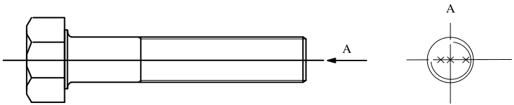
Figure description:
- Side view of a hexagonal head bolt with a central horizontal axis and an arrow labeled "A" pointing toward the threaded end.
- Cross-sectional view "A" showing a circular profile with crosshairs and three "x" symbols located along the horizontal axis.
4.3.3 Tensile test
4.3.3.1 Preconditions
- a. The tensile test method in 4.3.3.2 shall apply to finished fasteners having:
- a protruding head with grip length equal or greater than twice the nominal diameter, or
- a countersunk head and an overall length equal or greater than three times the nominal diameter, or
- a minimum length of 18 mm.
4.3.3.2 Method
-
a. Test jigs shall be designed and manufactured in accordance with ISO 3800.
-
b. Test jigs shall ensure a tensile loading parallel to the fastener main axis.
-
c. No torsional stress shall be induced by the assembly.
-
d. Specimens shall be assembled freely in the fixture without bending or forcing.
-
e. The bearing face of the threaded part of the jig, Figure 4-6 (a), or of the nut, Figure 4-6 (b), shall be located at least four pitches of distance from the unthreaded portion of the shank.
-
f. The nut threads shall be fully engaged.
-
g. A bolt length of at least two pitches shall protrude beyond the threaded part of the jig, Figure 4-6 (a), or the test nut, Figure 4-6 (b).
-
h. Test nuts shall be used only once.
-
i. When tested separately, axial load test of nuts shall be in accordance with clause 3.3 of ISO 9140.
-
j. Speed of testing shall be defined in terms of rate of separation of the two heads of the testing machine during a test.
-
k. Speed of testing shall not exceed 25 mm/min. NOTE Best practices is to maintain the speed of testing between 0,5 mm/min and 1,0 mm/min.
- Static failure shall only be tolerated in the shank.
- m. Fasteners with static failures occurring at the head-to-shank fillets shall be identified as nonconformant.
- n. The yield and ultimate tensile load of a tested fastener shall not be less than the values specified in the customer specification document for threaded fasteners.
- o. The cross sectional area, , used in the interpretation of the tensile test results, expressed in mm2, shall be assumed as the minimum of the two values and given by:
where:
- is the nominal pitch diameter in mm;
- the thread root nominal diameter in mm; and
the diameter of the minimum fastener cross sectional area if not in the threaded portion.
4.3.4 Shear test
4.3.4.1 Preconditions
- a. The shear test method in 4.3.4.2 shall apply to:
- finished fasteners of all sizes which meet one of the three requirements as specified in 4.3.3.1;
- fasteners with stepped threads (shouldered fasteners).
4.3.4.2 Method
- a. Shear test shall be carried out in double-shear loading configuration. NOTE Figure 4-7 shows an example of double-shear loading jigs.
- b. The shear loads to failure shall be no less than the allowable values specified in the customer specification document for threaded fasteners.
4.3.5 Fatigue test
4.3.5.1 General
- a. Fatigue tests shall be carried out in accordance with ISO 3800.
4.3.5.2 Preconditions
- a. The fatigue test method in 4.3.5.3 shall apply to finished fasteners of all sizes which meet one of the three requirements as specified in 4.3.3.1.
4.3.5.3 Method
- a. Fasteners shall be loaded in tension in accordance with one of the loading schemes shown in Figure 4-5.
- b. The fatigue test conditions shall be specified in the customer specification document for threaded fasteners in terms of:
- type of load fluctuation (sinusoidal unless otherwise agreed);
- stress range in MPa;
- stress ratio (R);
- frequency of load fluctuation in Hertz;
- specified mean and minimum fatigue life in cycles.
- c. The frequency of load fluctuation shall be
- between 4 Hz and 250 Hz; and
- such that the temperature of the test specimen measured at the first engaged thread is always less than 50°C.
- d. Stress calculation shall be based on the expressions for fastener cross sectional area given in 4.3.3.
- e. Fatigue strength values shall be determined in the finite life range (failure of all test pieces before a predetermined number of stress cycles is reached) and in the transition range where, up to a predetermined number (typically to ) of stress cycles, failure as well as non-failure occurs.
- f. All the tested fasteners shall exceed the minimum number of cycles specified for each applied stress range in the customer specification document for threaded fasteners.
- g. For fasteners with fatigue lives less than the expected mean fatigue life, failure shall not occur in the head-to-shank fillet.
NOTE No restrictions in failure location apply for fasteners with fatigue lives exceeding the expected mean fatigue life.
4.3.6 Creep test
4.3.6.1 General
-
a. The creep tests shall be carried out in accordance with ISO 204.
-
b. Calculations shall be based on the expressions for fastener cross sectional area given in 4.3.3.2o. NOTE 1 Creep test is particularly recommended for Titanium alloy fasteners. NOTE 2 For details see Annex B.
4.3.6.2 Method
- a. The percent elongation after fracture, the reduction of area at failure and the time to fracture shall be within the values specified in the customer specification document for threaded fasteners.
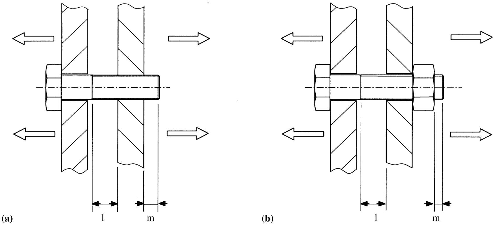
Figure description:
The provided image contains two schematics, (a and (b, illustrating tensile testing of threaded fasteners:
- Entities:
- Bolts: Two hex-head bolts inserted through vertical plates.
- Nut: Visible in schematic (b only, threaded onto the end of the bolt.
- Plates: Vertical cross-hatched sections representing the materials being fastened.
- Force Vectors: Horizontal arrows pointing away from the center, indicating tensile load.
- Dimension Lines: Marked as 'l' (length of the bolt shank between plates and 'm' (length of the threaded portion extending beyond the plate or nut.
- Key Differences:
- Image (a: Shows a bolt without a nut; the threads are on the end of the bolt shank.
- Image (b: Shows a bolt assembly with a nut tightened against the right plate.
- (l four times the thread pitch and m two times the thread pitch)
Figure 4‐6: Loading schematic for tensile testing of threaded fasteners
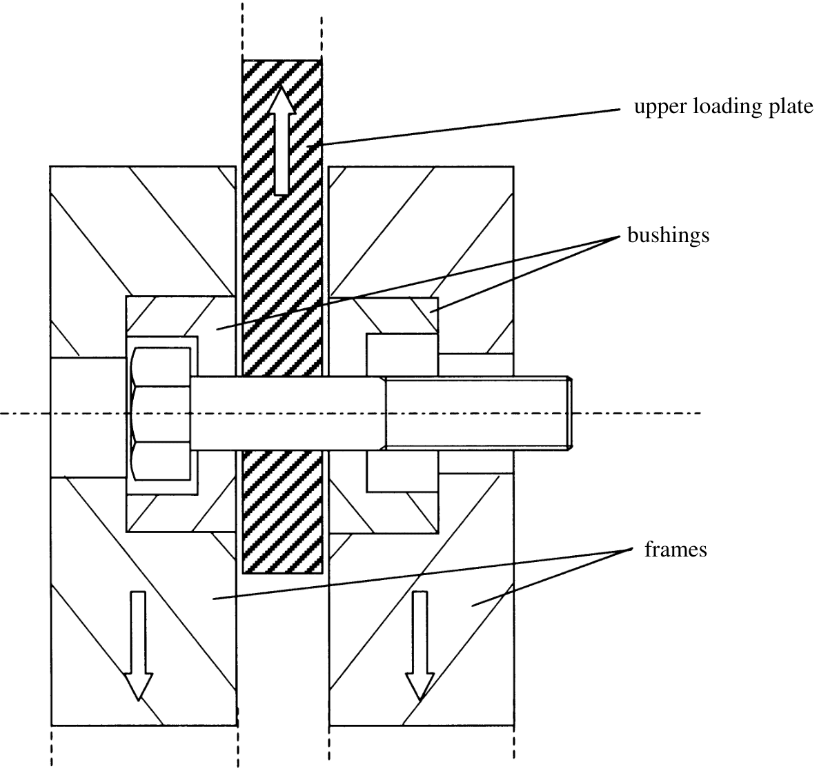
Figure description:
- upper loading plate: Central vertical component with upward-diagonal hatching and an upward-pointing arrow.
- bushings: Components positioned between the bolt and the frames.
- frames: Two outer vertical components with downward-diagonal hatching and downward-pointing arrows.
- bolt: A horizontal fastener passing through the frames, bushings, and upper loading plate, centered on a dashed-dotted horizontal line.
- Directional arrows: One upward arrow on the upper loading plate and two downward arrows on the frames.
- Dashed lines: Indicate continuation of the plate and frames at the top and bottom of the schematic.
Figure 4‐7: Schematic of an example of double‐shear loading jigs
4.3.7 Corrosion test
4.3.7.1 General
- a. Fasteners shall be tested for corrosion in accordance with ASTM B 117‐07a.
4.3.7.2 Method
- a. Sample geometry, exposure time and acceptance criteria shall conform to the requirements specified in the customer specification document for threaded fasteners.
- b. Metallic fasteners shall not be in contact with carbon fibre composite materials.
NOTE The reason is the considerable risk of corrosion.
4.3.8 Stress-corrosion test
- a. Stress‐corrosion testing shall be carried out in accordance with ECSS‐Q‐ST‐70‐37C.