4.2.1 General
- a. Dimensional and metallurgical controls shall be carried out in accordance with the sampling procedures and acceptance criteria specified in 4.4.2.1.
- b. Designation of dimensions and symbols shall be in accordance with ISO 225.
- c. Dimensional control of fasteners (bolts, nuts and studs) shall be carried out at room temperature (22 3) C.
- d. Gauges and measuring devices shall be in accordance with ISO 1502.
4.2.2 Nominal dimensions
- a. Nominal dimensions shall be in accordance with the detail drawings of the customer specification document for threaded fasteners.
- b. All dimensions shall refer to the final product and include any dimensional modification subsequent to chemically applied or electroplated coating.
- c. ISO 1502 standards on thread geometry and dimensions shall apply.
- d. Tolerances for fasteners shall be in accordance with national or international aerospace standards (e.g. LN, DIN aerospace standards) or meet or exceed tolerance values specified in ISO 4759‐1 for “Product grade A”.
4.2.3 Head-to-shank fillet
- a. The value of distortion shall not exceed 0,03 mm above and below the profile lines at points A and B in Figure 4‐1.
NOTE In bolts, cold rolling of head-to-shank fillets can cause distortion of fillet areas. Figure 4-1 shows the typical distortion of the head-to-shank fillet profile.
- b. The value of the extension C of the distorted area in Figure 4‐1 shall not exceed the values indicated in Table 4‐1.
Figure description:
The image contains the following information:
- Text: ECSS
- Visual Elements:
- The letter "E" is italicized and positioned within a white rectangular section.
- The letters "CSS" are positioned within a dark blue rectangular section.
- The entire logo is enclosed in a parallelogram with a dark blue border.
4.2.4 Non-destructive inspections
- a. Fasteners shall be free from surface defects such as flaws and inclusions.
- b. Inspections on bolts, studs and screws shall be carried out by using liquid penetrant or magnetic particles in accordance with ASTM E 1417-05e1 and ASTM E 1444-05, respectively.
- c. Non-destructive inspections shall be carried out by qualified personnel.
- d. Fasteners for safe-life applications shall be inspected as follows:
- using a 100 % batch inspection plan;
- by X-ray, ultrasonic or eddy current inspection methods to obtain 95 % (minimum) confidence level and 90 % (minimum) probability of defect detection.
- e. For fasteners for safe-life applications the results of NDI shall be evaluated in accordance with clause 10.3 of ECSS-E-ST-30-01C.
- f. Fasteners with detected surface defects shall be visually re-examined at ×15 (minimum) magnification factor.
| NOTE | An accurate measurement of the defect size can be obtained by metallographic examination in accordance with 4.2.5. |
|---|
- g. The following fasteners shall be declared as nonconformant:
- fasteners for fail-safe applications if the size of any defect is larger than the size specified in ISO 6157-2 and ISO 6157-3;
- fasteners for safe-life applications if the size of any defect is larger than the size specified in clause 10.3 of ECSS-E-ST-30-01C.
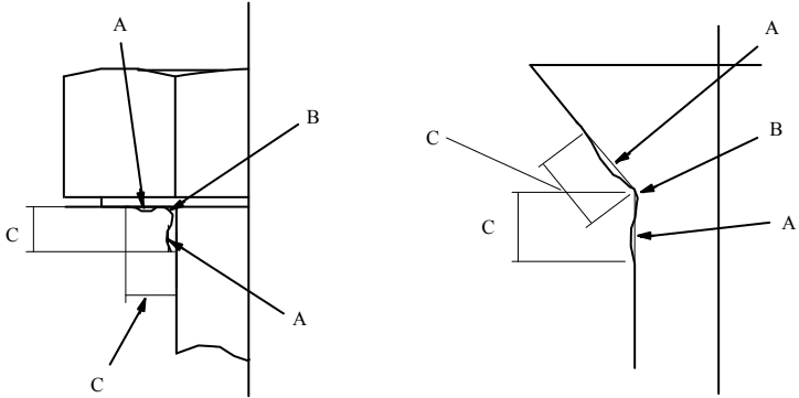
Figure description:
The image illustrates two technical diagrams related to fastener head-to-shank fillet profiles:
- Entity A: Points to irregular surface distortions or depressions along the fillet and shank areas.
- Entity B: Points to the junction or transition point between the head and the shank.
- Entity C: Indicates the linear extent or dimension of the distorted area (A, measured both vertically and horizontally in the left diagram and along the profile in the right diagram.
- Left Diagram: Depicts a fastener with a square or hexagonal head.
- Right Diagram: Depicts a fastener with a countersunk or tapered head.
| Nominal diameter, d (mm) | d<5 | 5≤d≤7 | 8≤d≤10 | 11≤d≤16 | 17≤d≤24 | d>24 |
|---|---|---|---|---|---|---|
| C maximum (mm) | 1,00 | 1,5 | 2,5 | 3,5 | 4,5 | 5,0 |

Figure description:
- Figure Title: Figure 4-2: Location of microsections for metallurgical examination.
- Component: Diagram of a bolt featuring a head, shank, and threaded section.
- Microsection Locations:
- 1: Longitudinal section (* through head and shank.
- 2: Transverse section (* through head.
- 3: Transverse section through head-to-shank transition zone.
- 4: Transverse section through shank.
- 5: Transverse section (* through shank-to-thread transition zone.
- 6: Transverse section through thread.
- Key: (* minimum required.
4.2.5 Metallurgical examination
- a. Fasteners selected for metallurgical examination shall be cut and prepared for observation in accordance with state‐of‐the‐art standard laboratory practice.
NOTE Figure 4‐2 shows the locations of microsections.
- b. Fasteners when visually examined at a magnification of between 10 and 50 shall exhibit a continuous grain flow in the head area and head‐to‐shank transition zone.
- c. Z values shall be equal to or less than the maximum fillet radius R (Z Rmax ) as specified in the detail drawings of the customer specification document for threaded fasteners.
NOTE Interruptions in grain flow within the area are defined by Z dimensions in Figure 4‐3.
- d. Fasteners when visually examined at a magnification of 50 shall exhibit continuous grain flow following the thread profile with maximum density of flow lines at thread roots.
NOTE For details see Figure 4‐4.
- e. Fastener microstructure shall be visually inspected for internal defects at a magnification of 100 or higher in un‐etched condition.
- f. Fastener microstructure shall be free from internal defects.
NOTE Internal defects are voids, cracks, inclusions, gross alloy segregation and indication of overheating.
- g. Surface coated or plated fasteners shall exhibit adequate thickness, uniformity and integrity of the protective layer.
- h. For fasteners in Titanium alloy strength class 1100 MPa, DIN ISO 9152 shall apply.
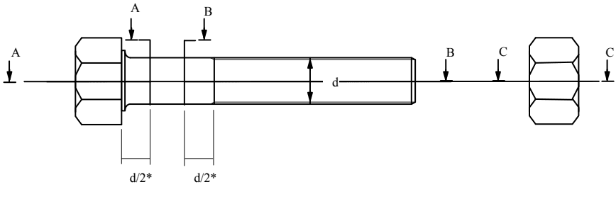
Figure description:
Technical diagram of a bolt and nut showing section locations for metallurgical examination:
- Entities: Hexagonal head bolt, threaded shank, hexagonal nut.
- Section A-A: Longitudinal section through the bolt head and upper shank.
- Section B-B: Longitudinal section through the mid-shank.
- Section C-C: Longitudinal section through the nut.
- Dimensions:
- d: Total diameter of the bolt shank.
- d/2*: Width of longitudinal section areas A and B indicated along the shank.
- Note: The asterisk (* indicates the minimum required area.
(*) minimum required
Figure 4‐2: Location of microsections for metallurgical examination

Figure description:
- Text: "E CSS"
- Graphical elements: Parallelogram with a blue border, divided into a white section (containing a blue "E" and a blue section (containing a white "CSS"
- Entity: ECSS logo
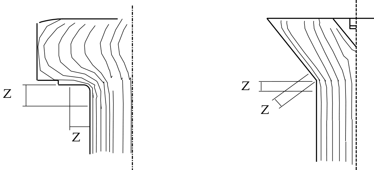
Figure description:
The image consists of two technical cross-section diagrams showing grain flow lines in fastener heads.
Left Diagram:
- Geometry: Right-angle transition between a fastener head and shank.
- Key Entities: Internal grain flow lines that curve from the shank into the head.
- Annotations: Two regions labeled "Z" indicate specific horizontal and vertical zones at the junction of the head and shank.
- Reference: A vertical dashed centerline on the right.
Right Diagram:
- Geometry: Countersunk or tapered transition between a fastener head and shank.
- Key Entities: Internal grain flow lines following the angled contour of the head.
- Annotations: Two regions labeled "Z" indicate specific zones along the transition area, one horizontal and one angled parallel to the head surface.
- Reference: A vertical dashed centerline on the right.
Figure 4‐3: Area delimiting interruptions in grain flow in the head‐to‐shank region
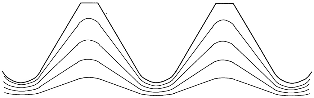
Figure description:
- Threaded surface profile featuring two trapezoidal peaks and rounded valleys.
- Five continuous, undulating internal lines following the contour of the surface profile.
- Key entities:
- Thread crests (flat-topped peaks
- Thread roots (curved valleys
- Internal grain flow lines (parallel, continuous wave patterns
Figure 4‐4: Example of a regular grain flow in a threaded surface
4.2.6 Measurement of hydrogen content
- a. Embrittlement by hydrogen absorption shall be prevented. NOTE Hydrogen contamination can cause embrittlement and degradation of mechanical properties of metals.
- b. Hydrogen content in fasteners shall be measured by an approved vacuum fusion or vacuum extraction method. NOTE Samples of material can be extracted from the fastener head after the removal of any surface coating.
- c. Hydrogen content in fully finished fasteners made of Titanium alloys shall not exceed 0,0125 %. NOTE Titanium alloys are particularly prone to embrittlement by hydrogen absorption.
4.2.7 Outgassing and offgassing
-
a. Thermal vacuum outgassing test in accordance with ECSS‐Q‐ST‐70‐02C shall be carried out on fasteners with organic inserts or collars, lubricants or protective substances if exposed to vacuum during service.
-
b. Offgassing test in accordance with ECSS‐Q‐ST‐70‐29C shall be carried out on fasteners with organic inserts or collars, lubricants or protective substances if used in crew compartments of manned space vehicles.