(This section contains information of a general or explanatory nature, which may be helpful but is not mandatory.)
6.1
Intended use. This standard defines and classifies galvanically dissimilar conductive materials and establishes requirements for protecting coupled dissimilar conductive materials against corrosion, with attention directed to the anodic member of the couple,. Previously, galvanic tables were based solely on the corrosion potentials of the two conductive materials in a galvanic couple. Since the potential difference does not incorporate kinetics, it is recognized that the galvanic potential difference between material couples is not a true indicator of galvanic corrosion. The new methodology incorporated into the “D” revision of MIL-STD-889 is based on the mixed potential theory of electrochemistry that was developed over 70 years ago and validated by electrochemists. Mixed potential theory states that the intersection points of two dissimilar conductive materials polarization curves can be used to determine the galvanic corrosion current and galvanic potential. Instead of crossing the anodic materials curve with the cathodic materials curve, the polarization curves of the anodic and cathodic materials were summed to produce a polarization curve of the joint sample in a 1:1 ratio. The galvanic current and potential obtained from the intersection point of the summed, joint curve can be used to determine the corrosion rate. The data collected in this standard was completed in static, immersed conditions.
6.4
Changes from previous issue. Marginal notations are not used in this revision to identify changes with respect to the previous issue due to the extent of the changes.
6.5
Calculation of corrosion rate . The corrosion rate for the anodic member in a galvanic couple and the self-corrosion rate of each conductive material (uncoupled) were determined using Faraday’s Law. The density and valence of the primary conductive material in the alloy were used in the calculation. Galvanic current and Icorr were collected using an artificial seawater solution. The listed corrosion rate and subsequent accelerating factors should not be the only determining factor in design decisions.
6.6
Summary of material properties. Table V lists the conductive materials tested within MIL-STD-889, along with their respective UNS codes. The table also lists treatments applied to the conductive materials and specific properties for applicable conductive materials.
6.7
Surface treatment notes in all tables. The following notes explain the surface treatment nomenclature found in the following tables of MIL-STD-889: Tables I, II, III, IV, C-1, C-II and C-III.
- a. The “T*” or “Tagnite” designation after a magnesium alloy indicates the Tagnite anodic coating which is a registered trademark of the Technology Applications Group, Inc.
- b. The “Cr3+ ”designation after an aluminum alloy indicates a trivalent conversion coating, while “Cr6+ ” designation indicates a hexavalent conversion coating.
- c. The “Zn-Ni w CC” designation indicates an IZ-C17 zinc-nickel plating with an IZ-264 trivalent conversion coating. IZ-C17 and IZ-264 are registered trademarks of Dipsol of America.
- d. The “Cadmium w CC” designation indicates cadmium plating with a traditional generic room temperature hexavalent conversion coating dip in a solution consisting of sodium dichromate and sulfuric acid.
9
TABLE I. Galvanic compatibility of bare conductive materials in a 1:1 A/C in immersed artificial seawater
| Cathodic Material | ||||||||||||||||||||||||||||||||||||||||||||||||
|---|---|---|---|---|---|---|---|---|---|---|---|---|---|---|---|---|---|---|---|---|---|---|---|---|---|---|---|---|---|---|---|---|---|---|---|---|---|---|---|---|---|---|---|---|---|---|---|---|
| 1 | 2 | 3 | 4 | 5 | 6 | 7 | 8 | 9 | 10 | 11 | 12 | 13 | 14 | 15 | 16 | 17 | 18 | 19 | 20 | 21 | 22 | 23 | 24 | 25 | 26 | 27 | 28 | 29 | 30 | 31 | 32 | 33 | 34 | 35 | 36 | 37 | 38 | 39 | 40 | 41 | 42 | 43 | 44 | 45 | 46 | 47 | ||
| Anodic Material | 1. Mg EV31 | 5 | 6 | 6 | 6 | 6 | 6 | 6 | 6 | 5 | 6 | 6 | 6 | 6 | 6 | 6 | 6 | 6 | 6 | 6 | 6 | 6 | 5 | 6 | 6 | 6 | 6 | 6 | 6 | 6 | 6 | 6 | 6 | 6 | 6 | 6 | 6 | 6 | 6 | 6 | 6 | 6 | 6 | 6 | 6 | 6 | 6 | |
| 2. Mg WE43 | 6 | 6 | 6 | 6 | 6 | 6 | 6 | 5 | 6 | 6 | 6 | 6 | 6 | 6 | 6 | 6 | 6 | 6 | 6 | 6 | 5 | 6 | 6 | 6 | 6 | 6 | 6 | 6 | 6 | 6 | 6 | 6 | 6 | 6 | 6 | 6 | 6 | 6 | 6 | 6 | 6 | 6 | 6 | 6 | 6 | |||
| 3. Mg AZ31B | 5 | 6 | 6 | 6 | 5 | 5 | 5 | 6 | 6 | 6 | 6 | 6 | 6 | 6 | 6 | 6 | 6 | 6 | 6 | 5 | 6 | 6 | 6 | 6 | 6 | 6 | 6 | 6 | 6 | 6 | 6 | 6 | 6 | 6 | 6 | 6 | 6 | 6 | 6 | 6 | 6 | 6 | 6 | 6 | ||||
| 4. Zinc | 5 | 3 | 5 | 3 | 4 | 3 | 5 | 5 | 5 | 6 | 6 | 3 | 6 | 5 | 6 | 5 | 5 | 4 | 4 | 5 | 5 | 5 | 5 | 5 | 6 | 5 | 5 | 5 | 5 | 5 | 5 | 5 | 5 | 5 | 5 | 5 | 5 | 5 | 5 | 3 | 6 | 6 | ||||||
| 5. Zn-Ni Plated | 3 | 5 | 3 | 4 | 4 | 5 | 5 | 5 | 5 | 5 | 4 | 5 | 5 | 5 | 5 | 4 | 4 | 4 | 5 | 5 | 5 | 5 | 5 | 6 | 4 | 5 | 5 | 5 | 5 | 5 | 5 | 5 | 5 | 5 | 5 | 5 | 5 | 5 | 4 | 5 | 6 | |||||||
| 6. Al5083 | 3 | 2 | 2 | 2 | 3 | 4 | 5 | 5 | 5 | 2 | 4 | 3 | 4 | 3 | 2 | 3 | 2 | 4 | 4 | 4 | 4 | 4 | 5 | 3 | 5 | 4 | 4 | 3 | 3 | 4 | 5 | 4 | 3 | 4 | 4 | 3 | 4 | 3 | 3 | 5 | 5 | |||||||
| 7. Cadmium | 4 | 5 | 4 | 5 | 5 | 5 | 5 | 5 | 4 | 5 | 5 | 5 | 5 | 5 | 5 | 4 | 5 | 5 | 5 | 5 | 5 | 6 | 5 | 5 | 5 | 5 | 5 | 5 | 5 | 5 | 5 | 5 | 5 | 5 | 5 | 5 | 5 | 5 | 6 | 5 | ||||||||
| 8. Al6061 | 2 | 2 | 3 | 4 | 5 | 5 | 5 | 2 | 4 | 3 | 4 | 3 | 2 | 3 | 2 | 4 | 4 | 4 | 4 | 4 | 5 | 3 | 5 | 4 | 4 | 3 | 3 | 4 | 5 | 4 | 3 | 4 | 4 | 3 | 4 | 3 | 3 | 5 | 5 | |||||||||
| 9. CP Aluminum | 2 | 3 | 4 | 5 | 5 | 5 | 2 | 4 | 3 | 4 | 3 | 2 | 3 | 2 | 4 | 4 | 4 | 4 | 4 | 5 | 3 | 5 | 4 | 4 | 3 | 3 | 4 | 5 | 4 | 3 | 4 | 4 | 3 | 4 | 3 | 3 | 5 | 5 | ||||||||||
| 10. A356 | 3 | 4 | 5 | 5 | 5 | 2 | 4 | 3 | 4 | 3 | 2 | 3 | 2 | 4 | 4 | 4 | 4 | 4 | 4 | 3 | 5 | 4 | 4 | 3 | 3 | 4 | 5 | 4 | 3 | 4 | 4 | 3 | 4 | 3 | 3 | 5 | 4 | |||||||||||
| 11. 1020 Steel | 4 | 5 | 5 | 5 | 3 | 4 | 4 | 4 | 4 | 3 | 3 | 3 | 4 | 4 | 4 | 4 | 4 | 5 | 3 | 4 | 4 | 4 | 3 | 3 | 4 | 4 | 4 | 3 | 4 | 4 | 3 | 4 | 3 | 3 | 5 | 4 | ||||||||||||
| 12. Al7075 | 5 | 5 | 5 | 4 | 5 | 5 | 5 | 5 | 4 | 5 | 4 | 5 | 5 | 5 | 5 | 5 | 5 | 5 | 5 | 5 | 5 | 4 | 5 | 5 | 5 | 5 | 5 | 5 | 5 | 5 | 5 | 5 | 4 | 5 | 5 | |||||||||||||
| 13. A36 Steel | 5 | 5 | 5 | 5 | 5 | 5 | 5 | 5 | 5 | 5 | 5 | 5 | 5 | 5 | 5 | 5 | 5 | 5 | 5 | 5 | 5 | 5 | 5 | 5 | 5 | 5 | 5 | 5 | 5 | 5 | 5 | 5 | 5 | 5 | ||||||||||||||
| 14. 1018 Steel | 5 | 4 | 5 | 5 | 5 | 5 | 4 | 5 | 4 | 5 | 5 | 5 | 5 | 5 | 5 | 5 | 5 | 5 | 5 | 5 | 5 | 5 | 5 | 5 | 5 | 5 | 5 | 5 | 5 | 5 | 5 | 5 | 5 | |||||||||||||||
| 15. 1008 Steel | 5 | 5 | 5 | 5 | 5 | 5 | 5 | 5 | 5 | 5 | 5 | 5 | 5 | 5 | 5 | 5 | 5 | 5 | 5 | 5 | 5 | 5 | 5 | 5 | 5 | 5 | 5 | 5 | 5 | 5 | 5 | 5 | ||||||||||||||||
| 16. Al7050 | 4 | 3 | 4 | 3 | 2 | 3 | 2 | 4 | 4 | 4 | 4 | 4 | 5 | 3 | 5 | 4 | 4 | 3 | 3 | 5 | 5 | 4 | 3 | 4 | 4 | 3 | 4 | 3 | 3 | 5 | 5 | |||||||||||||||||
| 17. B7 Steel | 4 | 4 | 4 | 3 | 4 | 3 | 4 | 4 | 4 | 4 | 4 | 5 | 4 | 4 | 4 | 4 | 3 | 4 | 4 | 5 | 4 | 4 | 4 | 4 | 4 | 4 | 3 | 5 | 4 | |||||||||||||||||||
| 18. MIL-11356 Steel | 4 | 3 | 3 | 3 | 3 | 4 | 4 | 3 | 3 | 4 | 4 | 3 | 4 | 4 | 4 | 3 | 3 | 4 | 4 | 4 | 3 | 3 | 4 | 3 | 3 | 3 | 3 | 5 | 4 | |||||||||||||||||||
| 19. 4340 Steel | 4 | 3 | 3 | 3 | 4 | 4 | 4 | 4 | 4 | 4 | 4 | 4 | 4 | 4 | 3 | 4 | 4 | 4 | 4 | 3 | 4 | 4 | 4 | 4 | 3 | 5 | 4 | |||||||||||||||||||||
| 20. HY80 Steel | 3 | 3 | 3 | 4 | 4 | 4 | 4 | 4 | 4 | 3 | 4 | 4 | 4 | 3 | 4 | 4 | 4 | 4 | 3 | 4 | 4 | 4 | 4 | 3 | 5 | 4 | ||||||||||||||||||||||
| 21. Tin | 3 | 1 | 4 | 4 | 4 | 4 | 4 | 2 | 3 | 3 | 3 | 3 | 2 | 2 | 3 | 3 | 3 | 2 | 3 | 3 | 3 | 2 | 3 | 5 | 5 | |||||||||||||||||||||||
| 22. Al2024 | 3 | 4 | 4 | 4 | 4 | 4 | 3 | 3 | 5 | 4 | 4 | 3 | 4 | 4 | 5 | 4 | 3 | 4 | 4 | 4 | 3 | 3 | 5 | 5 | ||||||||||||||||||||||||
| 23. Ti-6Al-4V | 3 | 2 | 3 | 2 | 3 | 1 | 1 | 1 | 1 | 1 | 1 | 1 | 1 | 1 | 1 | 1 | 1 | 1 | 1 | 1 | 2 | 2 | 2 | |||||||||||||||||||||||||
| 24. Brass, Yellow | 4 | 4 | 4 | 4 | 3 | 3 | 3 | 3 | 3 | 3 | 3 | 3 | 3 | 3 | 3 | 3 | 3 | 3 | 3 | 3 | 4 | 5 | ||||||||||||||||||||||||||
| 25. Bronze | 3 | 3 | 3 | 3 | 3 | 3 | 3 | 3 | 3 | 3 | 3 | 3 | 3 | 3 | 3 | 3 | 3 | 3 | 3 | 3 | 4 | |||||||||||||||||||||||||||
| 26. NiAl, C630 | 3 | 4 | 3 | 3 | 3 | 3 | 3 | 3 | 3 | 3 | 3 | 3 | 3 | 3 | 3 | 3 | 3 | 3 | 3 | 4 | 5 | |||||||||||||||||||||||||||
| 27. CuBe | 3 | 3 | 3 | 3 | 3 | 3 | 3 | 3 | 3 | 3 | 3 | 3 | 3 | 3 | 3 | 3 | 3 | 3 | 3 | 4 | ||||||||||||||||||||||||||||
| 28. CP Copper | 3 | 3 | 3 | 3 | 3 | 3 | 3 | 3 | 3 | 3 | 3 | 3 | 3 | 3 | 3 | 3 | 3 | 3 | 3 | 4 | ||||||||||||||||||||||||||||
| 29. PH 13-8 | 0 | 0 | 0 | 0 | 0 | 0 | 0 | 0 | 0 | 0 | 0 | 0 | 0 | 0 | 0 | 1 | 1 | |||||||||||||||||||||||||||||||
| 30. 304SS | 0 | 0 | 0 | 0 | 0 | 0 | 0 | 0 | 0 | 0 | 0 | 0 | 0 | 0 | 0 | 1 | ||||||||||||||||||||||||||||||||
| 31. PH 15-5 | 0 | 0 | 0 | 0 | 0 | 0 | 0 | 0 | 0 | 0 | 0 | 0 | 0 | 1 | 1 | |||||||||||||||||||||||||||||||||
| 32. 304SS Passivated | 0 | 0 | 0 | 0 | 0 | 0 | 0 | 0 | 0 | 0 | 0 | 0 | 0 | 1 | 1 | |||||||||||||||||||||||||||||||||
| 33. 410SS | 0 | 0 | 0 | 0 | 0 | 0 | 0 | 0 | 0 | 0 | 0 | 0 | 0 | 1 | ||||||||||||||||||||||||||||||||||
| 34. Inconel ® 600 | 0 | 0 | 0 | 0 | 0 | 0 | 0 | 0 | 0 | 0 | 0 | 1 | 1 | |||||||||||||||||||||||||||||||||||
| 35. A286 Passivated | 0 | 0 | 0 | 0 | 0 | 0 | 0 | 0 | 0 | 0 | 0 | 1 | ||||||||||||||||||||||||||||||||||||
| 36. PH 17-4 | 0 | 0 | 0 | 0 | 0 | 0 | 0 | 0 | 0 | 0 | 1 | |||||||||||||||||||||||||||||||||||||
| 37. 316SS | 0 | 0 | 0 | 0 | 0 | 0 | 0 | 0 | 0 | 1 | ||||||||||||||||||||||||||||||||||||||
| 38. 316SS Passivated | 0 | 0 | 0 | 0 | 0 | 0 | 0 | 0 | 1 | |||||||||||||||||||||||||||||||||||||||
| 39. Monel ® 400 | 0 | 0 | 0 | 0 | 0 | 0 | 1 | 1 | ||||||||||||||||||||||||||||||||||||||||
| 40. 410SS Passivated | 0 | 0 | 0 | 0 | 0 | 0 | 1 | |||||||||||||||||||||||||||||||||||||||||
| 41. A286 | 0 | 0 | 0 | 0 | 0 | 1 | ||||||||||||||||||||||||||||||||||||||||||
| 42. PH 17-4 Passivated | 0 | 0 | 0 | 0 | 1 | |||||||||||||||||||||||||||||||||||||||||||
| 43. PH 13-8 Passivated | 0 | 0 | 0 | 1 | ||||||||||||||||||||||||||||||||||||||||||||
| 44. PH 15-5 Passivated | 0 | 0 | 0 | |||||||||||||||||||||||||||||||||||||||||||||
| 45. Silver | 1 | 3 | ||||||||||||||||||||||||||||||||||||||||||||||
| 46. Graphite | 1 | |||||||||||||||||||||||||||||||||||||||||||||||
Legend : Galvanic compatibility between two conductive materials of interest is found at the intersection point of the row and column. The anodic member of the couple is listed in the rows and the cathodic member of the couple is listed in the columns. An empty cell at the intersection point indicates that the conductive material identified as anodic and cathodic should be switched. This table should not be used to indicate the level of risk associated with the galvanic couple nor should it be used to determine the level of protection required to protect the conductive materials. The CEA or appropriate design authority will determine the necessary protection. The corrosion rate was determined for conductive materials in a 1:1 surface area ratio. The number in the cells represent a range at which the anodic material will corrode when coupled with the cathodic material in artificial seawater. Any number above zero
indicates galvanic incompatibility. The range of the corrosion
on rate in mil/year is as follows: Galvanically Compatible: 0: <0.009 mil/year Galvanically Incompatible: 1: 0.01-0.09 mil/year 2: 0.1-0.9 mil/year 3: 1-4.99 mil/year 4: 5-9.99 mil/year 5: 10-99.99 mil/year 6: > 100 mil/year
Source: http://assist.dla.mil -- Downloaded: 2021-08-23T13:34Z Check the source to verify that this is the current version before use.
TABLE II. Galvanic compatibility of treated conductive materials in a 1:1 A/C in immersed artificial seawater
| Cathodic Material | |||||||||||||||
|---|---|---|---|---|---|---|---|---|---|---|---|---|---|---|---|
| a | b | c | d | e | f | g | h | i | j | k | l | m | n | ||
| Anodic Material | a. Mg WE43 T* | 5 | 5 | 5 | 5 | 6 | 5 | 5 | 5 | 5 | 6 | 5 | 5 | 6 | |
| b. Mg EV31 T* | 4 | 5 | 5 | 6 | 5 | 5 | 5 | 5 | 6 | 5 | 5 | 6 | |||
| c. Mg AZ31B T* | 5 | 4 | 5 | 5 | 5 | 5 | 4 | 6 | 5 | 5 | 6 | ||||
| d. Al5083 Cr+6 | 2 | 2 | 2 | 2 | 2 | 2 | 2 | 2 | 2 | 3 | |||||
| e. Al6061 Cr+6 | 2 | 2 | 2 | 2 | 2 | 2 | 2 | 2 | 3 | ||||||
| f. Al5083 Cr3+ | 2 | 2 | 2 | 2 | 2 | 2 | 2 | 2 | |||||||
| g. Al7075 Cr6+ | 2 | 2 | 2 | 2 | 2 | 2 | 4 | ||||||||
| h. Al6061 Cr+3 | 2 | 2 | 2 | 2 | 3 | 3 | |||||||||
| i. Cadmium w CC | 1 | 2 | 3 | 3 | 4 | ||||||||||
| j. Al7075 Cr+3 | 2 | 2 | 2 | 4 | |||||||||||
| k. Zn-Ni w CC | 3 | 3 | 4 | ||||||||||||
| l. Al2024 Cr6+ | 2 | 3 | |||||||||||||
| m. Al2024 Cr3+ | 3 | ||||||||||||||
| n. Electroless Ni | |||||||||||||||
Legend:
Galvanic compatibility between two conductive materials of interest is found at the intersection point of the row and column. The anodic member of the couple is listed in the rows and the cathodic member of the couple is listed in the columns. An empty cell at the intersection point indicates that the conductive materials identified as anodic and cathodic should be switched.
This table should not be used to indicate the level of risk associated with the galvanic couple nor should it be used to determine the level of protection required to protect the conductive materials. The CEA or appropriate design authority will determine the necessary protection.
The corrosion rate was determined for conductive materials in a 1:1 surface area ratio.
The number in the cells represent a range at which the anodic material will corrode when coupled with the cathodic material in artificial seawater. Any number above zero indicates galvanic incompatibility. The range of the corrosion rate in mil/year is as follows:
Galvanically Compatible: 0: <0.009 mil/year
Galvanically Incompatible:
- 1: 0.01-0.09 mil/year
- 2: 0.1-0.9 mil/year
- 3: 1-4.99 mil/year
- 4: 5-9.99 mil/year
- 5: 10-99.99 mil/year
- 6: > 100 mil/year
TABLE III. Galvanic compatibility of bare versus treated conductive materials in a 1:1 A/C in immersed artificial seawater
| a. Mg WE43 T* | b. Mg EV31 T* | c. Mg AZ31B T* | d. Al5083 Cr+6 | e. Al6061 Cr+6 | f. Al5083 Cr3+ | g. Al7075 Cr6+ | h. Al6061 Cr+3 | i. Cadmium w CC | j. Al7075 Cr+3 | k. Zn-Ni w CC | l. Al2024 Cr6+ | m. Al2024 Cr3+ | n. Electroless Ni | |
|---|---|---|---|---|---|---|---|---|---|---|---|---|---|---|
| 1. Mg EV31 | 5 | 5 | 5 | 6 | 6 | 6 | 6 | 6 | 6 | 6 | 6 | 6 | 6 | |
| 2. Mg WE43 | 5 | 5 | 5 | 6 | 6 | 6 | 6 | 6 | 6 | 6 | 6 | 6 | 6 | |
| 3. Mg AZ31B | 5 | 5 | 5 | 5 | 5 | 6 | 5 | 5 | 5 | 5 | 6 | 5 | 5 | 6 |
| 4. Zinc | 5 | 5 | 5 | 2 | 2 | 2 | 3 | 3 | 4 | 2 | 4 | 3 | 3 | 5 |
| 5. Zn-Ni Plated | 6 | 6 | 6 | 3 | 3 | 3 | 3 | 3 | 3 | 3 | 4 | 4 | 4 | 5 |
| 6. Al5083 | 6 | 6 | 5 | 2 | 2 | 2 | 2 | 2 | 2 | 1 | 2 | 2 | 3 | 4 |
| 7. Cadmium | 6 | 6 | 6 | 3 | 3 | 3 | 3 | 3 | 4 | 4 | 5 | 5 | 5 | 5 |
| 8. Al6061 | 5 | 5 | 4 | 2 | 2 | 2 | 2 | 2 | 2 | 1 | 2 | 2 | 2 | 3 |
| 9. CP Aluminum | 5 | 5 | 5 | 2 | 2 | 2 | 2 | 2 | 3 | 2 | 3 | 3 | 3 | 4 |
| 10. A356 | 5 | 5 | 4 | 2 | 2 | 2 | 2 | 2 | 2 | 2 | 2 | 2 | 2 | 3 |
| 11. 1020 Steel | 6 | 6 | 6 | 3 | 3 | 3 | 3 | 3 | 4 | 3 | 3 | 3 | 3 | 3 |
| 12. Al7075 | 6 | 6 | 6 | 4 | 4 | 4 | 4 | 4 | 5 | 4 | 4 | 4 | 4 | 5 |
| 13. A36 Steel | 6 | 6 | 6 | 5 | 5 | 5 | 5 | 5 | 5 | 5 | 5 | 5 | 5 | 5 |
| 14. 1018 Steel | 6 | 6 | 6 | 5 | 5 | 5 | 5 | 5 | 5 | 5 | 5 | 5 | 5 | 5 |
| 15. 1008 Steel | 6 | 6 | 6 | 5 | 5 | 5 | 5 | 5 | 5 | 5 | 5 | 5 | 5 | 5 |
| 16. Al7050 | 6 | 6 | 5 | 2 | 2 | 2 | 2 | 2 | 2 | 2 | 2 | 2 | 3 | 4 |
| 17. B7 Steel | 6 | 6 | 6 | 4 | 4 | 4 | 4 | 4 | 5 | 4 | 4 | 3 | 3 | 4 |
| 18. MIL-11356 Steel | 6 | 6 | 6 | 3 | 3 | 3 | 3 | 3 | 4 | 3 | 3 | 3 | 3 | 3 |
| 19. 4340 Steel | 6 | 6 | 6 | 4 | 4 | 4 | 4 | 4 | 5 | 4 | 4 | 3 | 3 | 4 |
| 20. HY80 Steel | 6 | 6 | 6 | 3 | 3 | 3 | 3 | 3 | 4 | 3 | 4 | 3 | 3 | 4 |
| 21. Tin | 6 | 6 | 5 | 2 | 2 | 2 | 2 | 2 | 2 | 1 | 2 | 1 | 1 | 2 |
| 22. Al2024 | 6 | 6 | 6 | 3 | 3 | 3 | 3 | 3 | 4 | 3 | 3 | 3 | 3 | 4 |
| 23. Ti-6Al-4V | 5 | 5 | 5 | 2 | 2 | 2 | 2 | 2 | 2 | 1 | 2 | 1 | 1 | 1 |
| 24. Brass, Yellow | 6 | 6 | 6 | 4 | 4 | 3 | 4 | 4 | 5 | 4 | 4 | 4 | 4 | 3 |
| 25. Bronze | 6 | 6 | 6 | 4 | 4 | 3 | 4 | 4 | 5 | 4 | 4 | 4 | 4 | 3 |
| 26. NiAl, C630 | 6 | 6 | 6 | 4 | 4 | 3 | 4 | 4 | 5 | 4 | 4 | 4 | 4 | 3 |
| 27. CuBe | 6 | 6 | 6 | 4 | 4 | 3 | 4 | 4 | 5 | 4 | 4 | 4 | 4 | 3 |
| 28. CP Copper | 6 | 6 | 6 | 4 | 4 | 3 | 4 | 4 | 5 | 4 | 5 | 4 | 4 | 3 |
| 29. PH 13-8 | 6 | 6 | 6 | 4 | 4 | 2 | 3 | 4 | 5 | 4 | 5 | 2 | 2 | 2 |
| 30. 304SS | 6 | 6 | 6 | 3 | 3 | 2 | 3 | 3 | 4 | 3 | 3 | 3 | 3 | 2 |
| 31. PH 15-5 | 6 | 6 | 6 | 5 | 4 | 2 | 5 | 5 | 5 | 5 | 5 | 4 | 4 | 2 |
| 32. 304SS Passivated | 6 | 6 | 6 | 4 | 4 | 2 | 4 | 4 | 5 | 4 | 5 | 4 | 4 | 2 |
| 33. 410SS | 6 | 6 | 6 | 4 | 4 | 2 | 4 | 4 | 5 | 4 | 5 | 4 | 4 | 2 |
| 34. Inconel® 600 | 6 | 6 | 6 | 3 | 3 | 2 | 3 | 3 | 3 | 3 | 3 | 3 | 2 | 2 |
| 35. A286 Passivated | 6 | 6 | 6 | 3 | 3 | 2 | 3 | 3 | 4 | 3 | 4 | 3 | 3 | 2 |
| 36. PH 17-4 | 6 | 6 | 6 | 4 | 4 | 2 | 4 | 4 | 5 | 4 | 5 | 4 | 3 | 2 |
| 37. 316SS | 6 | 6 | 6 | 5 | 5 | 2 | 5 | 5 | 5 | 5 | 5 | 5 | 4 | 2 |
| 38. 316SS Passivated | 6 | 6 | 6 | 4 | 4 | 2 | 4 | 4 | 5 | 4 | 4 | 4 | 3 | 2 |
| 39. Monel® 400 | 6 | 6 | 6 | 3 | 3 | 2 | 3 | 3 | 4 | 3 | 3 | 2 | 2 | 2 |
| 40. 410SS Passivated | 6 | 6 | 6 | 4 | 4 | 2 | 4 | 4 | 5 | 4 | 4 | 3 | 3 | 2 |
| 41. A286 | 6 | 6 | 6 | 4 | 4 | 2 | 4 | 4 | 5 | 4 | 4 | 4 | 3 | 2 |
| 42. PH 17-4 Passivated | 6 | 6 | 6 | 3 | 3 | 2 | 3 | 3 | 4 | 3 | 4 | 3 | 3 | 2 |
| 43. PH 13-8 Passivated | 6 | 6 | 6 | 4 | 4 | 2 | 4 | 4 | 5 | 4 | 4 | 3 | 3 | 2 |
| 44. PH 15-5 Passivated | 6 | 6 | 6 | 3 | 3 | 2 | 3 | 3 | 4 | 3 | 4 | 3 | 3 | 2 |
| 45. Silver | 6 | 6 | 5 | 3 | 3 | 2 | 3 | 3 | 3 | 3 | 3 | 3 | 3 | 2 |
| 46. Graphite | 6 | 6 | 6 | 5 | 5 | 2 | 5 | 5 | 5 | 5 | 5 | 5 | 5 | 2 |
| 47. Platnium | 6 | 6 | 6 | 4 | 4 | 2 | 4 | 4 | 5 | 5 | 5 | 4 | 4 | 3 |
Legend:
Galvanic compatibility between two conductive materials of interest is found at the intersection point of the row and column. Bare materials are listed in the rows and treated materials are listed in the columns. To determine the anodic member of the couple, Table IV should be used.
This table should not be used to indicate the level of risk associated with the galvanic couple nor should it be used to determine the level of protection required to protect the conductive materials. The CEA or appropriate design authority will determine the necessary protection.
The corrosion rate was determined for conductive materials in a 1:1 surface area ratio
The number in the cells represent a range at which the anodic material will corrode when coupled with the cathodic material in artificial seawater. Any number above zero indicates galvanic incompatibility. The range of the corrosion rate in mil/year is as follows:
Galvanically Compatible:
0: <0.009 mil/year
Galvanically Incompatible:
- 1: 0.01-0.09 mil/year
- 2: 0.1-0.9 mil/year
- 3: 1-4.99 mil/year
- 4: 5-9.99 mil/year
- 5: 10-99.99 mil/year
- 6: > 100 mil/year
TABLE IV. Galvanic series of selected conductive materials in immersed artificial seawater according to ASTM D1141 (without heavy metals). 1/
| Active (More Active - Anodic) | |||
|---|---|---|---|
| Magnesium WE-43 Tagnite | Tin | ||
| Magnesium EV-31 | Al2024 | ||
| Magnesium EV-31 Tagnite | Al2024 Cr+6 | ||
| Magnesium WE-43 | Al2024 Cr+3 | ||
| Magnesium AZ31-B Tagnite | Ti-6Al-4V | ||
| Magnesium AZ31-B | Electroless Nickel | ||
| Al5083 Cr+6 | Brass, Yellow | ||
| Zinc | Bronze | ||
| Al6061 Cr+6 | NiAl Alloy C630 | ||
| Al5083 Cr+3 | CuBe | ||
| Al7075 Cr+6 | Copper | ||
| Zn-Ni Plated | PH 13-8 | ||
| Al6061 Cr+3 | 304SS | ||
| Al5083 | PH 15-5 | ||
| Cadmium | Passivated 304SS | ||
| Al6061 | 410SS | ||
| Cadmium w/ Conversion Coating | Inconel® 600 | ||
| Aluminum | Passivated A286 | ||
| Al7075 Cr+3 | PH 17-4 | ||
| A356 | 316SS | ||
| 1020 Steel | 316SS Passivated | ||
| Al7075 | Monel® 400 | ||
| Zn-Ni with Conversion Coating | 410SS Passivated | ||
| A36 Steel | A286 | ||
| 1018 Steel | PH 17-4 Passivated | ||
| 1008 Steel | PH 13-8 Passivated | ||
| Al7050 | PH 15-5 Passivated | ||
| B7 Steel | Silver | ||
| MIL-11356 Steel | Graphite | ||
| 4340 Steel | Platinum | ||
| HY80 Steel | |||
| Continued in column 2… | Noble (Less Active - Cathodic) | ||
| MIL-STD-889D Nomenclature | UNS Code | Properties | Characteristic Tested in MIL-STD-889D |
| A356 | A13560 | Bare | |
| CP Aluminum | A91100 | Bare | |
| Al2024 | A92024 | Heat Treat: T-3; SAE AMS4037 | Bare, Cr⁶⁺, Cr³⁺ |
| Al5083 | A95083 | Alloy H-32 | Bare, Cr⁶⁺, Cr³⁺ |
| Al6061 | A96061 | Heat Treat: T-6 | Bare, Cr⁶⁺, Cr³⁺ |
| Al7050 | A97050 | Bare | |
| Al7075 | A97075 | Heat Treat: T-6 | Bare, Cr⁶⁺, Cr³⁺ |
| CP Copper | C10100 | Bare | |
| CuBe | C17000 | Bare | |
| Bronze | C22000 | Commercial Bronze C-220 | Bare |
| Brass, Yellow | C26800 | Alloy CA-260; ASTM B36/B36M | Bare |
| NiAl C630 | C63000 | Bare | |
| 1008 Steel | G10080 | Bare | |
| 1018 Steel | G10180 | Bare | |
| 1020 Steel | G10200 | SAE 1020, Cold-rolled | Bare |
| B7 Steel | G41400 | Bare | |
| 4340 Steel | G43400 | AISI 4340 | Bare |
| MIL11356 Steel | J13025 | Bare | |
| HY80 Steel | J42015 | Bare | |
| A36 Steel | K02600 | Bare | |
| Cadmium | L01951 | SAE AMS-QQ-P-416 | Bare, Conversion Coated |
| Mg AZ31 | M11311 | Bare, Tagnite | |
| Mg EV31 | M12310 | Bare, Tagnite | |
| Mg WE43 | M18430 | Bare, Tagnite | |
| Monel® 400 | N04400 | Alloy 400 | Bare |
| Inconel® 600 | N06600 | Alloy 600 | Bare |
| Platinum | P04995 | Bare | |
| Silver | P07010 | Bare | |
| Ti-6Al-4V | R56400 | SAE AMS-T-9046, Composition C, Type III | Bare |
| PH 13-8 | S13800 | SAE AMS5629D; Heat treat: solution treated | Bare, Passivated |
| PH 15-5 | S15500 | Bare, Passivated | |
| PH 17-4 | S15700 | ASTM A693-06 Type 630 | Bare, Passivated |
| 304SS | S30400 | Bare, Passivated | |
| 316SS | S31600 | AISI 316 | Bare, Passivated |
| 410SS | S41000 | Bare, Passivated | |
| A286 | S66286 | SAE AMS5525K Cold Rolled, Annealed | Bare, Passivated |
| Zinc | Z15006 | Bare | |
| Graphite | NA | Bare | |
| Tin | NA | ASTM B339A(b) | Bare |
| Zn-Ni Plated | NA | ASTM B841 | Bare, Conversion Coated |
- 1/ This table should not be used for the determination of compatibility. This table should only be used for determining the anodic member of a galvanic couple. To determine which material is the anodic member of a galvanic couple, locate both materials on the galvanic series table. The material “higher” in the series (closer to the more active side) will be the anodic member. The material “lower” in the series (closer to the less active side) will be the cathodic member.
TABLE V. Description of materials used to obtain data
SURFACE PROTECTIVE TREATMENTS
A.1 SCOPE
A.1.1 Scope. This appendix lists recommended corrosion protection systems (coatings and surface finishes) for conductive materials and alloys. Selection of protection schemes require approval from the Cognizant Engineering Authority (CEA) or appropriate design authority. The CEA should account for any applicable environmental regulations or restrictions in the selection of the protection schemes. Alterations in either the protection scheme or the material to which the protection scheme is applied, requires approval from the CEA or appropriate design authority. This Appendix is not a mandatory part of this standard. The information contained herein is presented for guidance only.
A.1.2 Application. This appendix outlines the recommended protective treatments for common conductive materials and alloys used in dissimilar conductive material couples. These protective treatments should be used when galvanically incompatible materials are joined together. Environmental conditions to which the couple is expected to be subjected in-service must be taken into account. Considerations must be given to the following factors: operational conditions, electrical requirements, design requirements, and minimization of maintenance and cost. Initial increase in costs can be more than offset by reduced maintenance and repair and increased service life of the part. Specific review of proposed protective systems for dissimilar conductive material couples should be performed and authorized by the CEA or appropriate design authority prior to their introduction or adoption.
A.2 APPLICABLE DOCUMENTS
A.2.1 Specifications. The following specifications form a part of this document to the extent specified herein. Unless otherwise specified, the issues of these documents are those cited in the solicitation or contract.
FEDERAL SPECIFICATION
TT-C-490 - Chemical Conversion Coatings And Pretreatments For Metallic Substrates (Base For Organic Coatings)
DEPARTMENT OF DEFENSE SPECIFICATIONS
MIL-DTL-5002
Surface Treatments and Inorganic Coatings for Metal Surfaces of Weapons Systems MIL-C-8514
Coating Compound, Metal Pretreatment, Resin-Acid (ASG) MIL-PRF-8625
Anodic Coatings For Aluminum and Aluminum Alloys MIL-DTL-16232
Phosphate Coating, Heavy, Manganese or Zinc Base MIL-C-17711
Coatings, Chromate, For Zinc Alloy Castings and Hot-dip Galvanized Surfaces MIL-DTL-18264
Finishes, Organic, Weapons Systems, Application and
APPENDIX A
Control of MIL-DTL-32119
Coatings, Electroless Nickel, Special Applications MIL-DTL-81706 Chemical Conversion Materials for Coating Aluminum and Aluminum Alloys
DEPARTMENT OF DEFENSE STANDARDS
MIL-STD-171
Finishing of Metal and Wood Surfaces MIL-STD-7179
Finishes, Coatings, and Sealants, for the Protection of Aerospace Weapons Systems and Support Equipment
(Copies of these documents are available online at https://assist.dla.mil.)
A.2.2 Non-Government publications. The following documents form a part of this document to the extent specified herein. Unless otherwise specified, the issues of these documents are those cited in the solicitation or contract.
ASTM INTERNATIONAL
ASTM A967/A967M: Standard Specification for Chemical Passivation Treatments for Stainless Steel Parts ASTM D1732: Standard Practices for Preparation of Magnesium Alloy Surfaces for Painting
(Copies of these documents are available online at http://www.astm.org.)
SAE INTERNATIONAL
SAE AMS2700 - Passivation of Corrosion Resistant Steels SAE AMS2487 - Anodic Treatment of Titanium and Titanium Alloys Solution pH 12.4 Maximum SAE AMS2488 - Anodic Treatment - Titanium and Titanium Alloys Solution pH 13 or Higher SAE AMS-C-8837 - Coating, Cadmium (Vacuum Deposited) SAE AMS-C-26074 - Coatings, Electroless Nickel Requirements for SAE AMS-C-81562 - Coatings, Cadmium, Tin-Cadmium and Zinc (Mechanically Deposited) SAE AMS-M-3171 - Magnesium Alloy, Processes for Pretreatment and Prevention of Corrosion on SAE AMS-QQ-P-416 - Plating, Cadmium (Electrodeposited) SAE AS12500 - Corrosion Prevention and Deterioration Control in Electronic Components and Assemblies
( Copies of these documents are available online at http://www.sae.org.)
A.3 Surface preparation for protective scheme treatment. Cleaning, prior to application of surface treatments and coatings should follow MIL-DTL-5002, MIL-STD-171, TT-C-490 or other appropriate specification as approved by the CEA or appropriate design authority.
A.4 Corrosion protection. Protection schemes for various conductive materials and metal alloy groups are recommended. Within each category, the protection schemes are listed in decreasing order of protectiveness. Application specific protective schemes are also recommended below. Protective schemes should be selected with consideration to the factors listed in A.1.2, opting for the most stringent protective scheme possible. Specific enhancing effects can be accomplished by selecting a higher-level treatment for each conductive material in the couple. Protective schemes should be designed for both the anodic and cathodic member of the galvanic couple. Redundant protection (i.e., combinations of recommended protection schemes) is recommended when design permits. Surface pretreatments, passivation treatments, metallic coatings, insulating shims or gaskets, primers, topcoats and sealants should all be considered by the CEA or appropriate design authority for inclusion in the design of the part or component to preclude or minimize the risk of dissimilar conductive material corrosion.
The protection schemes described in this appendix are recommended to protect against galvanic corrosion. Additional corrosion protections may be required to protect the materials from other types of corrosion such as pitting or crevice corrosion.
NOTE: Many coatings and platings may have a detrimental effect on the fatigue life of base metals and alloys. The CEA or appropriate design authority is responsible for accounting for any loss in fatigue properties and the implementation of methods to prevent fatigue property loss (i.e., shot peening to impart surface compressive stresses, etc.), if necessary.
A.4.1 Treatment for magnesium and magnesium alloys
- a. Anodic coating (ASTM D1732) post-treated with an alkali-resistant paint or resin coating system. Fayed surfaces should be protected according to MIL-STD-7179.
- b. For general use in non-persistent wet or marine atmosphere an anodic coating without organic coating system; chromate conversion coating (SAE AMS-M-3171) post-treated with an alkali-resistant paint or resin coating system.
- c. For electrical, thermal conducting purposes, in absence of wet, saline or acidic atmospheric conditions: Metallic coating, electroless nickel (SAE AMS-C-26074, or MIL-DTL-32119 where applicable) with cadmium over plating (SAE AMS-QQ-P- 416).
- d. Chromate treatment. Suitable for assured condensation-free and acid-free conditions.
Note: Bare magnesium should not be used. Magnesium and magnesium alloys should not be used in Naval applications unless approved by the CEA or appropriate design authority.
A.4.2 Treatment for zinc and zinc coatings
- a. Anodic coating post-treated with a paint or resin coating system, primarily for castings.
- b. For electrical and thermal conducting purposes in mild atmospheres in the absence of wet, saline or acidic conditions: Chromate conversion coating (MIL-C-17711) post treated with a paint or resin coating system or anodic coating without organic coating system.
- c. Chromate conversion coating without paint or resin coating system. Note: Bare zinc plated should not be used in a marine environment.
A.4.3 Treatment for lead, tin, solders and indium coatings. Coatings of these materials applied to other metals by hot-dipping, fusing, or electroplating processes
- a. Coat with paint or resin coating system. Electroplated coatings should be flowed (i.e., wetted) prior to applying coating system.
- b. Electroplate with other metal to reduce the electropotential difference of metals being joined, where direct contact of metals is required for electrical purposes.
NOTE: For more information on electronics and avionics corrosion, prevention and control (CPC) requirements, refer to SAE AS12500.
A.4.4 Treatment for cadmium (SAE AMS-QQ-P-416, SAE AMS-C-8837 or SAE AMS-C-81562) or beryllium
- a. Chromate conversion coating post-treated with a paint or resin coating system.
- b. For electrical and thermal conducting purposes in mild atmospheres in absence of wet, saline or acidic conditions: Chromate conversion coating without an organic coating system. Recommended for beryllium in high temperature applications to forestall catastrophic oxidation in an oxygen-containing atmosphere.
A.4.5 Treatment for aluminum and aluminum alloys
- a. Anodize to produce a coating according to MIL-PRF-8625 and post-treat with a corrosion resistant finish approved by the CEA or appropriate design authority. Hot water seal should not be used unless authorized by the CEA or appropriate design authority. Parts subject to wear, abrasion, erosion, and severe corrosion should not be anodized unless authorized by the CEA or appropriate design authority and the detrimental effects on fatigue life are accounted for in the design of the part.
- b. Chromate conversion coating (MIL-DTL-81706) post treated with a paint or
resin coating system; or anodic coating, sealed, with resin seal (when porous castings are used, impregnated with resin prior to surface treating and finishing). This is required for locations classified as exterior aircraft surfaces by MIL-STD-7179, unless identified by the CEA or appropriate design authority.
- c. For electrical and thermal conducting purposes in mild atmospheres in absence of saline, alkaline or acidic conditions: Chromate conversion coating without paint or resin coating system. NOTE: Bare aluminum - may be used when surface treating would interfere with application, under conditions free of salinity or extended wetness, or when the alloy has sufficient corrosion resistance for the application. Faying edges should be sealed to prevent crevice corrosion.
A.4.6 Treatment for carbon and low alloy steels
- a. Apply an appropriate corrosion protective coating to the surface of the steel as specified by the CEA or appropriate design authority for the specific dissimilar material coupling, environment and unique design requirements. Protective coatings include, but are limited to, nickel, copper, zinc, cadmium, chromium, aluminum, nickel boron, nickel cadmium, electroless nickel, zinc-nickel, thermal spray coatings, ceramic coatings, etc. Not all combinations of corrosion protective coatings and steel alloys are compatible (e.g. the selection of an appropriate coating can be dependent on the heat treatment (mechanical properties) of the steel). Some of the metallic coatings are used specifically for corrosion protection (e.g. cadmium, aluminum, zinc-nickel, etc.) while others are used for other engineering purposes yet still provide effective corrosion protection (e.g., engineering hard chrome (EHC) plating and nickel plating for wear applications). The CEA or appropriate design authority must balance all design requirements to select and specify the coating system that provides maximum corrosion protection while also meeting all other design requirements. When the design permits, the CEA or appropriate design authority should also specify corrosion protective surface treatments, primers, paints, resin coatings and sealants that can be applied over the dissimilar metal couple or faying edges of the dissimilar metal couple. Barrier gaskets, protective films and other electrically insulating technologies should also be included if design requirements permit. Detailed requirements for corrosion protection coatings, finishes and sealants are provided in other standards and specifications such as MIL-STD-7179, TT-C-490, MIL-STD-171.
- b. Application of metallic coatings without supplemental sealant, primer, paint or resin coating may be necessary in some designs. For applications requiring high electrical or thermal conductivity or in designs where use of supplemental protection such as sealants, primers, paints or resin coatings is not feasible, use metallic coatings as specified by the CEA.
- c. Special purpose chemical conversion coatings and pretreatments for metallic
substrates (base coatings for organic coatings) such as zinc phosphates and iron phosphates (TT-C-490), resin acid pretreatments (MIL-C-8514) and manganese or zinc base heavy phosphate conversion coating (MIL-DTL-16232) can improve both corrosion protection and primer and topcoat adhesion. Use of these conversion coatings on steels that are susceptible to hydrogen embrittlement require that the CEA or appropriate design authority define the pre- and post-processing precautions discussed in A.4.6.e.
- d. Surface finishing requirements for steel surfaces of military hardware and vehicles are also included in MIL-STD-171. This standard covers surface cleaning methods, electroplating, conversion coatings, wash primers, paint primers and topcoats. It is the responsibility of the CEA or appropriate design authority to specify the surface finish requirements necessary to meet the design requirements.
- e. Prevention of Hydrogen Embrittlement (HE) of high strength steels during manufacture or rework: Steels heat-treated to an ultimate tensile strength (UTS) of 180 KSI (Rockwell C scale hardness of 40) or higher are susceptible to hydrogen embrittlement. Many coatings and coating processes have the potential to cause HE of steels. Designs calling for the use of coatings or coating deposition processes that can cause HE must specify specific processing requirements to both prevent and eliminate HE. Preventive measures may include reducing high residual surface tensile stresses through thermal stress relieving, or imparting beneficial compressive stresses to the surface by shot peening and careful control of the coating deposition process to minimize the evolution of hydrogen during the deposition process. Some specifications for coatings or coating deposition processes specify periodic testing of coupons to assess and control the process. Elimination of HE (de- embrittlement) of high strength steels following coating deposition is by low temperature heating (baking) of the part or component in air for specific time periods (normally 375 ± 25 ˚F (190.5 ± 13.9˚C) for non-surface hardened parts and 275 ± 25 ˚F (135 ± 13.9˚C) for carburized or nitrided parts for 23 hours). The requirements for prevention and elimination of HE in high strength steels vary widely within both government and industry specifications and standards. It is the responsibility of the CEA or appropriate design authority to define the specific engineering requirements for the prevention and elimination of HE of steels based on the requirements of the governing specification, unique design requirements, and engineering best practices.
A.4.7 Treatment for titanium and titanium alloys
- a. Anodize for anti-galling and wear resistance. Application of primer coating or sealant should be applied according to MIL-STD-7179 to faying surfaces. Metals should be anodized according to SAE AMS2487 and SAE AMS2488.
- b. Apply metallic coating post-treated with a paint or resin coating system.
Caution: Titanium and titanium alloys can be susceptible to metal-induced embrittlement (MIE) in contact with some low melting metals including cadmium, zinc, and silver. MIE can occur as either solid metal or liquid metal embrittlement. Use of cadmium and zinc in contact with titanium or titanium alloys is prohibited. Silver plating over an underplating of nickel is permitted.
- c. For electrical or thermal conducting purposes, apply metallic coating (Cd, Zn prohibited, Ag over Ni acceptable), seal faying edges.
- d. For electrical or thermal conducting purposes, titanium may be used bare with faying edges sealed as stated in MIL-STD-7179. Use of bare titanium is prohibited when titanium is in contact with magnesium, zinc, silver, or cadmium.
A.4.8 Treatment for electrically conductive composites.
- a. Apply a non-conductive layer (such as fiberglass ply) as a barrier ply to the composite surface. Prime and fay surface seal the metallic surface to preclude moisture. Fastener materials for use in carbon fiber reinforced composite structures should be titanium, A286, or Inconel 718 or other approved fasteners (i.e., pre-coated, etc.). Additional protection can be afforded using sealant to wet install the fasteners.
A.4.9 Treatment for graphite
- a. Plate graphite with a conductive material that is galvanically compatible to both the graphite and the conductive material it is joined to minimize galvanic current. If service is electrical, seal faying edges to preclude corrosion at contacting surface of the conductive material member or apply a conformal coating according to MIL-STD-7179.
- b. Graphite may be used bare in electrical or thermal conducting service, conditions permitting. Faying edges should be sealed.
A.4.10 Treatment for austenitic, precipitation hardening (PH), ferritic (200 series) and martensitic (400 series) stainless steels
-
a. Passivation: Stainless steels (200, 300, 400 series) and precipitation-hardened stainless steels should be passivated in accordance with ASTM A967/A967M or SAE AMS2700, or by other methods approved by the CEA or appropriate design authority. Passivation should be followed by a thorough rinsing and drying. Passivation is not required for corrosion resistant steels that are to be inorganically coated.
-
b. Martensitic and PH stainless steels heat treated to HRC 40 or above require HE prevention and relief processing as defined in A.4.6.e.
-
c. Austenitic and PH stainless steels can be used effectively in dissimilar conductive material couples by using insulating gaskets and/or applying primers, paints or other organic coatings without application of metallic coatings. Primers, paint and sealants should be considered for faying surface edges.
-
d. Apply appropriate metallic coatings to the surface of the steel as specified by the CEA or appropriate design authority for the specific dissimilar conducive material coupling, environment, and design requirements. When the design permits, the CEA or appropriate design authority should also specify corrosion protective surface treatments, primers, paints, resin coatings and sealants that can be applied over the metallic coatings or faying edges of the couple. A wide variety of surface treatments, primers, paints, resin coatings are available for corrosion protection of stainless steels in various corrosive environments. Barrier gaskets, protective films and other electrically insulating technologies should also be included if design requirements permit. Detailed requirements for corrosion protection coatings, finishes and sealants are provided in other standards and specifications such as MIL-STD-7179, TT-C-490, and MIL-STD-171, etc.
-
e. Ferritic and martensitic stainless steels used in dissimilar conductive material couples should be coated or plated with metallic coatings followed by treatment with primers, paints or other corrosion protective coatings.
-
A.4.11 Treatment for copper and copper alloys. Copper and copper alloys include pure copper, bronze, brass, aluminum bronzes, phosphor bronzes, nickel aluminum bronze and copper beryllium alloys.
-
a. Copper and copper alloy part surfaces should be passivated if applicable for the specific alloy. The CEA or appropriate design authority should select the optimum metallic coating, such as cadmium, nickel-cadmium, tin-cadmium, tin-lead, tin, zinc, nickel, or metallic-ceramic to minimize galvanic incompatibility.
-
b. When the design permits, the CEA or appropriate design authority should also specify corrosion protective surface treatments, primers, paints, resin coatings and sealants that can be applied over the metallic coatings or faying edges of the couple. A wide variety of surface treatments, primers, paints, resin coatings are available for corrosion protection of copper and copper alloys in various corrosive environments. Barrier gaskets, protective films and other electrically insulating technologies should also be included if design requirements permit. Detailed requirements for corrosion protection coatings, finishes and sealants are provided in other standards and specifications such as MIL-STD-7179, TT-C-490, MIL-STD-171, etc.
A.4.12 Treatment for chromium (chrome) plating
- a. Engineering hard chrome plating extending beyond the faying surfaces of a dissimilar coupling and exposed to a corrosive environment that does not provide sufficient corrosion protection of the substrate should have an undercoat of 0.0010 to 0.0016 inch of nickel on steel or zinc parts or an undercoat of 0.0008 to 0.0010 inch of nickel on copper alloy parts.
- b. Craze cracks in “runout” areas of engineering hard chrome plate may be sealed with organic coatings or dry film lubricants to prevent moisture intrusion on parts that do not have nickel underplating. Sealing of craze cracking in chrome plating should not be done in areas of the plating subjected to sliding wear or contact with seals and wiper rings.
A.4.13 Treatment for silver
- a. Silver or silver plated parts to be used as electrical, open-close contact points, plugs and receptacles should be plated over with rhodium, palladium, or gold.
- b. May be used in stationary components of electrical assemblies, e.g., connectors, printed circuits, but should be enveloped by sulfur-free conformal coatings.
- c. Apply chromate conversion coating post treated with a corrosion inhibiting fluid film to parts of electrical plugs, receptacles, etc.
A.4.14 Treatment for rhodium, palladium, gold, platinum and their alloys. Use bare, with compound sealant at edges of dissimilar conductive material joint, or by enveloping dissimilar conductive material joint in conformal coatings, where feasible.
MATERIAL PREPARATION AND ACQUISITION OF POLARIZATION DATA
B.1 SCOPE
B.1.1 Scope. This appendix is intended for the collection of polarization data for MIL-STD-889. The purpose of this appendix is to provide the procedure that ensures, to the best extent possible, the uniform collection of electrochemical data, which reduces variability and allows for comparison between laboratories and samples. This appendix lists the requirements for laboratories generating data under MIL-STD-889. This appendix also includes information regarding the stringency in the procedures and lessons learned to help laboratories troubleshoot potential issues with data collection. This appendix is required for accurate generation and replication of polarization data for purposes of MIL-STD-889. This Appendix is a mandatory part of the specification. The information contained herein is intended for compliance.
B.1.2 Application. The sample preparation processes used to prepare the samples for testing is described. The data collection, transformation, and other best practices used in the creation of this standard are outlined.
B.2 APPLICABLE DOCUMENTS
B.2.1 Non-Government publications. The following documents form a part of this document to the extent specified herein. Unless otherwise specified, the issues of these documents are those cited in the solicitation or contract.
ASTM INTERNATIONAL
ASTM D1141 - Standard Practice for the Preparation of Substitute Ocean Water ASTM E178 - Standard Practice for Dealing with Outlying Observations
(Copies of these documents are available online at http://www.astm.org.)
B.3 GENERAL REQUIREMENTS
B.3.1 Data validation and verification. Information pertaining to generation or submission of data in accordance with MIL-STD-889 can be obtained from Commander, Naval Air Warfare Center, Aircraft Division (NAWCAD), Air Systems Group (ASG): Corrosion and Wear Branch, Code AB23600, 48066 Shaw Rd, Bldg 2188, Unit 5, Patuxent River, MD 20670-1161. New polarization data for galvanic couples not currently contained in this Standard or new polarization data that differs from that currently in this standard shall be sent to the NAWCAD ASG: Corrosion and Wear Branch prior to data being accepted under MIL-STD-889. NAWCAD ASG: Corrosion and Wear Branch reserves the right to reject any data based on discrepancies seen with the listed samples. To provide validation and verification, the submitting entity must provide data for a galvanic couple of bare aluminum 7075 T-6 and bare 1020 carbon steel, cold-rolled in additional to the data for the new material. All information to be presented is listed in B.3.7.
B.3.2 Surface preparation. The following procedures shall be used when preparing samples of bulk materials for data generation under MIL-STD-889.
-
a. Machining: The surface shall be milled or ground to remove surface features and obtain the bulk microstructure.
-
b. Surface finish: The surface of the conductive materials shall be ground with P800 (or ANSI 400) grinding paper for surfaces representative of non-functional or bare surfaces. The surface undergoing test shall be ground to a uniform finish. Grinding paper shall be aluminum oxide-based for softer conductive materials (e.g., aluminum and magnesium alloys) and silicon carbide-based for harder conductive materials (see B.4 for exceptions and discussion). NOTE: Grinding media and grit size can affect the results of electrochemical testing. Grinding aluminum alloys with silicon carbide can embed silicon in the sample surface, which will affect the polarization curve. The grit size used for grinding the sample directly relates to the surface roughness and thus the surface area of the sample.
-
c. Samples with grease or oil on the surface require a degreasing step prior to final surface preparation. To degrease the samples, a 4-step sonication process shall be completed in the following order: (1) ACS grade hexanes, (2) ACS grade diethyl ether, (3) ACS grade acetone, and (4) 200-proof ethanol. The samples shall be fully immersed and sonicated in each chemical for 10-minutes. Observe the safety regulations of your facility when using an ultrasonic cleaner with flammable solvents.
-
d. Surface preparation: Following grinding with P800 or ANSI 400 abrasive paper, test samples shall be ultrasonically cleaned immediately using ACS grade acetone for 10 minutes followed by 200 proof ethanol for 10 minutes, and air- dried at room temperature. Observe the safety regulations of your facility when using an ultrasonic cleaner with flammable solvents.
-
e. Samples requiring any further treatment (e.g., passivation, anodization, plating, etc.) must be prepared in accordance with B.3.2 prior to treatment and cleaned following treatment using acetone and ethanol.
-
f. Immediately following cleaning, specimens shall be placed in a chamber maintaining 77 ±0.63 ˚F (25 ±0.35 ˚ C) and 80 percent relative humidity for twenty-four (24) hours before testing (see B.4 for more discussion). Testing shall commence immediately after the twenty four (24)-hour humidity period. Materials showing signs of staining or corrosion shall be rejected for testing and reprepared according to B.3.2.
-
g. Samples prone to crevice corrosion during testing (e.g., some stainless steels) shall be masked to avoid the crevice formed by the interface with the O-ring on the electrochemical cell. Masking material shall be chemically resistant to the electrolyte used in the electrochemical test, potential compounds that are produced as a result of the test, and acidic or basic pH levels. The masking material shall also be free from conducting elements.
-
h. Each test requires a freshly prepared sample in accordance with steps a–f.
B.3.3 Electrochemical cell. Polarization curves shall be collected using an electrochemical flat cell. Regardless of manufacturer of the flat cell, ensure the following:
- a. The O-rings used to seal the working electrode are chemically resistant to the electrolyte used in the electrochemical test, side products produced as a result of the test, and acidic or basic pH levels. The O-rings shall also be free from conducting elements (see B.4 for more discussion).
- b. The counter electrode shall be inert. The counter electrode shall be at least twice the area of the working electrode so that the current the counter electrode provides to or accepts from the working electrode is not limited. A platinum mesh counter electrode is recommended.
- c. The counter electrode shall be arranged in a parallel orientation to the working electrode.
- d. The reference electrode shall be placed in a bridge cell or Luggin tube between the working and counter electrodes. The tip of the bridge cell or Luggin tube shall be placed as close to the surface of the working electrode as possible, ensuring no electric current shielding takes place during the polarization scan. The distance from the bridge cell or Luggin tube to the working electrode will vary based on the diameter of the tip of the bridge cell or Luggin tube.
- e. The electrochemical cell shall be placed in a Faraday cage to minimize noise in the data.
B.3.4 Reference electrode. The most common reference electrodes along with their conversion factors are provided in Table B-I:
TABLE B-I. Summary of common reference electrodes
| Reference Electrode | Potential (V vs. ESHE) | Potential (V vs. SCE) |
|---|---|---|
| Standard Hydrogen Electrode | 0.00 | -0.241 |
| Ag/AgCl, saturated KCl | +0.199 | -0.042 |
| Saturate Calomel Electrode | +0.241 | 0.00 |
| Copper Sulfate, saturated | +0.318 | +0.077 |
Any other reference electrode that is properly maintained and compatible with the electrolyte is acceptable. (See B.3.5 for maintenance recommendations.)
B.3.5 Reference electrode maintenance. A health check of the reference electrode shall be completed against an unused reference electrode of the same type (i.e., SCE to SCE) to ensure that no additional systematic errors are introduced to the measured data. An unused reference electrode shall be properly stored and maintained in its filling solution. The unused reference
electrode shall only be used to compare with other reference electrodes and shall not be used for polarization measurements. This reference electrode shall be replaced every 6-12 months with a new one to ensure the health of the unused electrode. To check if the reference electrode being used for an electrochemical test is within a correct range:
- Place the unused reference electrode and the reference electrode to be checked in a small container with electrolyte (KCl or NaCl).
- Measure the potential difference between the two electrodes using a digital multimeter or potentiostat, with the reference to be checked connected as working electrode and the unused reference connected as reference electrode using the Open Circuit Potential (OCP) measurement mode. The measured potential shall be equal to or less than 5.0 mV for a period of 15 minutes when checking, e.g., SCE vs SCE of standard. If this is not the case, the test reference electrode may need new filling solution or the frit may need replacement. If the frit is replaced, adequate time must be given for the frit to become wet. Refer to the manufacturer’s instructions for the amount of time to wetness.
B.3.6 Electrolyte. The electrolyte used for the data collection for MIL-STD-889 is artificial seawater in accordance with ASTM D1141, without heavy metals. The solution can be commercially acquired or prepared in-house per the standard. If prepared in-house, use de- ionized water (18 MΩ-cm) to prepare the electrolyte. In addition, if prepared in-house, the solution shall be prepared at least twenty-four (24) hours prior to the beginning experiment. The electrolyte shall be aerated vigorously for 10 minutes immediately before use in an electrochemical test but left quiescent (naturally aerated) for the duration of the test, at 25 ± 1.67 °C (77 ± 3 °F), and with pH 8.2. A pH check shall be performed prior to the beginning of the test. See Section B.4.5 for instructions on adjusting the pH.
B.3.7 Polarization curve data acquisition. Pre-Test Data Measurements: The following data shall be provided to NAWCAD Air Systems Group, Corrosion and Wear Branch for both anodic and cathodic test specimens. Failure to provide all required data may delay or prevent acceptance of polarization curves:
- OCP vs. time:
- a. Sampling Period – a sampling period of 1 data point per second for 24 hours (for more noble, OCP > -200 mV vs. SCE) and 4 hours (for less noble, OCP < -200 mV vs. SCE) conductive materials during surface stabilization in the test cell.
- Polarization parameters:
- a. A full polarization curve shall consist of a cathodic curve and anodic curve generated with separate specimens, respectively. According to Table B-II, anodic curves shall be generated from OCP to +0.7 V vs. OCP, or when the anodic current density reaches a maximum current of 10 mA/cm 2. Cathodic curves shall be generated from OCP to -1.4 V vs. SCE, or when the cathodic current density reaches a maximum current of 10 mA/cm 2.
- Material Characteristics:
- a. Substrate material
- b. Heat treatment condition, specification, lot number, etc. of the material
- c. Dimensions of the sample (thickness, length, width, area of sample exposed for
testing)
- d. Grinding media size and type (e.g., SiC or Al2 O3 )
- e. All data on surface preparation method (grinding and surface profiling, heat treating, cleaning, coating, time since prepared, etc.)
- All relevant data defining the polarization test measurements:
- a. Electrolyte chemistry
- b. Type of reference electrode (including reference check values)
- c. Scan rate of polarization curve
- d. Temperature
- e. Humidity
- f. pH of electrolyte (before and after testing)
- g. Test cell manufacturer/part number including all dimensional specifications on size, shape and positioning of the working electrode, counter electrode, and reference electrode.
B.3.8 Data reproducibility. At a minimum, three (3) complete data sets shall be taken (anodic and cathodic curves) in order to determine the spread in the data for a given material. A summary of the conditions and parameters for polarization measurements is presented in Table B-II.
TABLE B-II. Summary of parameters for polarization data
| Item | Notes | |
|---|---|---|
| Equipment | Electrochemical cell. | |
| Reference electrode | SCE, Ag/AgCl, or other suitable electrode. | |
| Electrolyte | Artificial sea water per ASTM D1141 without heavy metals, 25 ± 1.67 °C (77 ± 3 °F), pH 8.2 ± 0.02, vigorously aerated (10-20 minutes) prior to testing, then quiescent condition (naturally aerated; no bubbling) | |
| Working electrode | Specimen to be tested. Stationary. Abraded with appropriate P800 or ANSI 400 grinding paper, cleaned with acetone then ethanol, and surface treated appropriately (if required). | |
| OCP stabilization | The surface should be stabilized in the electrolyte, but not for a time that causes the surface condition to change significantly (e.g. crevice or pitting): | |
| MORE Noble (OCP > -200 mV vs. SCE): | LESS Noble (OCP < -200 mV vs. SCE): | |
| 24 hours in electrolyte prior to polarization measurement | 4 hours in electrolyte prior to polarization measurement | |
| Polarization curve | - Anodic polarization: OCP to +0.7 V vs. OCP, or when the anodic current density reaches a maximum current of 10 mA/cm² - Cathodic polarization: OCP to -1.4 V vs. SCE, or when the cathodic current density reaches a maximum current of 10 mA/cm² Note: Cathodic and anodic curves shall be obtained on separate specimens prepared according to B.3.2. | |
| Sweep rate | 100 µV/s for entire potential range | |
| IR correction | The reference electrode should be placed >2x diameter of Luggin tip from the working electrode. | |
B.4 Notes. The following notes provide additional information for troubleshooting purposes and exceptions to the procedure outlined.
B.4.1 Exceptions to material preparation. Preparation of soft materials (i.e., lead, silver, and magnesium) may require hand polishing. To hand polish, the following procedure shall be used. Materials shall be polished using the grinding paper listed in B.3.2.
- Polish the conductive material in straight lines.
- Rotate the conductive material 90 degrees and polish in straight lines.
- Repeat until the surface is free from defects and is uniform.
- Rinse the surface with a reagent grade acetone followed by a rinse in 200-proof ethanol. Then place in the humidity chamber for 24 hours.
Note: To achieve a consistent measurement for lead, gentle wiping with a lint-free, 1-ply Kimwipe was required prior to mounting the sample for testing.
B.4.2 O-rings. Selected O-rings in contact with the sample, shall be resistant to chemicals that are present in the electrolyte, side products produced during the electrochemical test, and acidic or basic pH levels. The O-rings shall also be free from conducting elements. O-rings that easily break down in the chemical or pH environment can affect the results of the electrochemical test by changing the exposed surface area or adding additional components to the chemistry of the electrolyte. Although the pH of the artificial seawater specified in this document is slightly basic, acidic conditions may develop local to the surface in the crevice formed by the O-ring, which will cause rapid degradation of the O-ring.
It is preferred that O-rings be replaced between runs. If this is not practical, O-rings shall be thoroughly cleaned between runs. Contaminants on the O-Ring could cause changes in the pH close to the surface of the test sample and affect the results of the electrochemical test.
B.4.3 Sample storage prior to testing. To ensure uniform results, samples shall be stored in a temperature and humidity controlled chamber at 77 ± 0.63 ⁰F (25 ± 0.35 ⁰C) and 80 percent relative humidity for 24 hours prior to testing. If corrosion, such as flash corrosion, or staining develops during the 24 hour period prior to testing, the sample shall be re-prepared according to the steps outlined in B.3.2. While more surface characterization is required to test this hypothesis, it is suspected that these conditions create a uniform type, quality, and/or thickness of the oxide layer on the sample.
B.4.4 Polarization curve test parameters. Polarization curves shall be run at a scan rate of 100 µV/s, starting at the Open Circuit Potential of the sample. Both the scan rate and the starting point of polarization curves will affect the results of the test. High scan rates can skip over polarization curve features because the surface cannot stabilize at the speed of the test. Low scan rates can allow the surface to over-stabilize and produce results such as unstable passivation on aluminum. Starting even 5-10 mV away from OCP (either anodic or cathodic) will affect the sample’s surface and change the electrochemical data that is collected.
B.4.5 pH variabilities. To ensure there is no drift in the pH, prior to testing, the pH of the solution shall be measured and adjusted to 8.2 ±0.02 using sodium hydroxide or hydrochloric acid, as appropriate. Dilution of the sodium hydroxide and hydrochloric acid using 18 MΩ-cm
deionized water will prevent large shifts in the pH when adjusting.
B.4.6 OCP variabilities. If the user has followed the procedures outlined in this document and large variations in OCP are witnessed, this may be a result of the interaction of the conductive material surface and the electrolyte that is close to a transition in the respective Pourbaix diagram. For instance, a pH of 8.2 is close to the active/passive line in the Pourbaix diagram for Aluminum 7075-T6. Minor fluctuations in the pH local to the surface caused by any factor including the cleanliness of the O-ring and flat cell could shift the surface to either side of the passive/active line. This results in large disparities in the open circuit potential of the samples. For Al 7075-T6, the OCP in the passive region is about -750 mV vs. SCE and the OCP in the active region is about -1000 mV vs. SCE.
B.4.7 Connection issues with potentiostat. The following is a list of issues that may indicate that there is a connection problem with the leads from the potentiostat:
- a) An OCP that is drastically different from anticipated
- b) An OCP that varies very linearly over time
- c) An OCP that is sensitive to movement and presence of people nearby
- d) Deposits on the counter electrode
Potential causes with their solutions of these connection issues are shown in Table B-III.
TABLE B-III. Potential causes of potentiostat connection issues
| Potential Causes | Solution |
|---|---|
| Air bubbles in the Luggin tube or bridge cell | Gentle tapping or a piece of thin tubing inserted into Luggin Tube/bridge cell |
| Corrosion on metallic connectors (on alligator clips, banana clips, connection plates, etc.) | Replace connectors or remove corrosion from the metallic connectors |
| Poor metallic-metallic interface between connection plate and sample (e.g., material from a mask causing a gap and poor interface with the connection plate) | Etch material where the connector is attached or remove mask from that area of the connector. |
| Deposit on the counter electrode | Clean counter electrode appropriately (for platinum mesh counter electrode, soak in 50 percent nitric acid overnight) |
B.4.8 Post-processing transformation. To ensure consistency in polarization curve analysis, all polarization curves shall be normalized to units of mA/cm 2 prior to post-processing. This allows for reasonable comparisons across electrochemical cell configurations.
B.4.8.1 Pairing polarization data. Anodic and cathodic curves shall be paired into complete polarization curves before comparison on replicate trials. The most important criteria in combining anodic and cathodic polarization curves for a given conductive material is the alignment of OCP values. OCP is the strongest indicator of consistent surface preparation between polarization curves of the same conductive material. Aligned OCP values indicate the conductive material began each test with similar surface conditions.
B.4.8.2 Deconvolution overview. Deconvolution of the polarization curves is required to obtain electrochemical parameters used in the calculation of corrosion rates. Deconvolution shall be completed following the method outlined in An Iterative Method For Fitting Complex Electrode Polarization Curves by K.S. Yeum and O.F. Devereux, Corrosion, Vol. 45, pp. 478-487 (1989). The deconvolution process determines the contributions of individual electrochemical reactions to the complete polarization curve. The total current of a given polarization curve is the result of a summation of the contributions of individual electrochemical reactions. These individual reactions take on a roughly exponential form with respect to potential. An individual electrochemical reaction can be approximated with the following six reaction types, where different rate limiting features are dominant.
- Charge Transfer Control
- Passivation
- Diffusion Limited
- Ohmic drop
- Diffusion Limited w/Ohmic Drop
- Passivation w/Ohmic Drop
The process uses regression algorithms to determine constants for each reaction equation that best fits the contributions of these individual reactions to the provided polarization curve.
To eliminate operator bias, three independent operators perform the deconvolution process on three separate polarization curves for each given sample type. The goal is to obtain consensus on the reactions present in each polarization curve. After a consensus of reaction types is achieved, each operator performs deconvolution according to the agreed upon reaction types. Each operator must then take an average of each reaction’s constants across the three fit polarization curves. Then, the global average of the three operators’ averaged results is completed.
B.4.8.3 Outlier analysis. To ensure data integrity, outlier analysis shall be performed according to ASTM E178. Utilize the Student’s t-test method with a 0.01 significance level for each averaged reaction constant as described in 7.1.1 of ASTM E178. Remove user’s deconvolution datasets with reaction constants that exceed the 0.01 significance level for equality of mean.
B.4.8.4 Generating an individual material polarization curve. After the deconvolution and averageng processes for the individual reactions are completed, the averaged reactions shall be used to generate an averaged polarization curve. This shall be completed with a simple sum in current across the potential. This method takes into account the three polarization curves collected and deconvoluted by each operator.
MIL-STD-889D APPENDIX B
B.4.8.5 Generating a joint sample polarization curve. The averaged polarization curves can then be utilized to determine properties of the galvanic coupling. First, sum the anodic reactions of both conductive materials. Then, sum the cathodic reactions of both conductive materials. The intersection point of the summed anodic reactions with the summed cathodic reactions provides the galvanic potential and current. Galvanic potential is the potential value at the intersection point. Galvanic current is the current value at the intersection point.
PRINCIPLES OF GALVANIC CORROSION
C.1 SCOPE
C.1.1 Purpose. This appendix explains the principle factors that are involved in the phenomenon of galvanic corrosion. This Appendix is not a mandatory part of this standard. The information contained herein is presented for guidance only.
- C.1.2 Application. The principle factors involved in the phenomenon of galvanic corrosion are explained.
C.2 GENERAL INFORMATION
C.2.1 Factors influencing galvanic corrosion. Several factors can influence the kinetics of galvanic corrosion. Among these are the polarization behavior of the conductive materials under the prevailing conditions; the areas of the anode and cathode; the electrical resistance; the type and concentration of the electrolyte; the pH of the electrolyte medium; the distance between, and the geometry of, the anode and cathode; and the degree of aeration or motion of the electrolyte medium. Basic factors are the electrical potentials of the electrodes, current, and resistances, expressed by
Where is the potential of the cathode (as polarized); is the potential of the anode (as polarized); is the current in amperes; is the resistance of the electrolyte solution path in the galvanic current (internal circuit) and is the resistance of the electrodes (external circuit).
C.2.2 Corrosive environment. Each conductive material, in an electrolyte at a specific concentration and temperature, has a specific electrical potential, i.e., ability to undergo dissolution - to form metal ions with the release of electrons. In a corrosive solution having high conductivity and producing readily soluble corrosion products of the conductive materials, corrosion will continue. In a limited volume of solution, where conditions are more likely to develop that will hamper corrosion, e.g., increase of concentration of metal ions, the corrosion will diminish with time. In contrast, the same conductive material as the anode of a galvanic couple will tend to exhibit accelerated corrosion, which can be related to a flow of current in the circuit if the cathode is unaffected by polarization. If the electrodes polarize progressively, galvanic current flow and corrosion will subside and may actually stop. Generally, the rate of corrosion will decrease with higher concentrations of the electrolyte or with lower temperature.
a. Galvanic effects may change because of different pH conditions within an electrolyte. A conductive material, which is the anode in a neutral or acidic solution, may become the cathode if the solution is basic.
- b. Oxygen dissolved in the electrolyte can depolarize the cathode by oxidizing absorbed hydrogen. In some cases, oxygen may be necessary to promote oxidation of the anode. The
amount of available oxygen and the rate of its diffusion therefore can change the rate of galvanic attack.
- c. Ions, which are generated at the electrode as corrosion proceeds, concentrate at or near the electrode surfaces (polarization) and impede current flow. For each of these cases, in static solutions, the corrosion action is diffusion-dependent and is under diffusion control. Agitation of the solution will increase the reaction rate.
- C.2.3 Conductivity of the galvanic circuit. Corrosion of a single conductive material in an electrolyte involves the flow of current from local anodic to local cathodic areas on the conductive material surface. This is termed "local cell corrosion" and is the situation of normal corrosion. Relatively small differences in potentials of local cells are the result of compositional dissimilarities on the conductive material surface because of different conductive material phases or crystal orientation, crystal imperfections segregations, grain boundaries, and other conditions. The more inhomogeneous the surface, the more susceptible it is to general attack. Dissolution of the anode relates to the galvanic current. According to Faraday's law,
where W is the mass or quantity of conductive material dissolved, in grams; I is the current in amperes; t is the time of current flow, in seconds; e is the equivalent of the anode conductive material (atomic weight divided by valence or charge of ions produced); F is Faraday’s constant (96,5000 coulombs per mol).
Galvanic corrosion is different from corrosion of a single conductive material experiencing current flow in an electrolyte solution. The latter type of corrosion is caused by differences in oxygen content of the electrolyte solution at different surfaces of the conductive material; differences in solute ion concentration or differential aeration; or differential ion or concentration.
C.2.4 Components of polarization curve. To understand the components of a polarization curve, it is first necessary to understand an Evans Diagram. Figure C-1 illustrates an Evans diagram with an arbitrary scale. It is typical to see the data plotted with a logarithmic current, leading to a linear plot. The slope of the line is called the Tafel slope and is usually expressed in mV/decade.
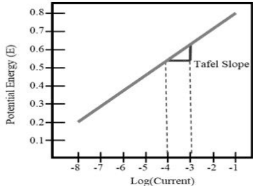
Figure description:
Annotations
- Tafel Slope (text_label - position: adjacent to the data line between x = -4 and x = -3)
- measurement boundary (vertical_line - position: x = -4)
- measurement boundary (vertical_line - position: x = -3)
| Log(Current) | Potential Energy (E) |
|---|---|
| -8 | 0.2 |
| -7 | 0.29 |
| -6 | 0.37 |
| -5 | 0.46 |
| -4 | 0.54 |
| -3 | 0.63 |
| -2 | 0.71 |
| -1 | 0.8 |
Notes: The plot displays the linear relationship between the logarithm of current and potential energy (Tafel plot. The slope indicated between Log(Current values of -4 and -3 is labeled as the 'Tafel Slope'.))
FIGURE C-1. Evans diagram with an arbitrary scale.
There are two common cathodic reactions in polarization curves: hydrogen evolution reactions (HER) and oxygen reduction reactions (ORR). HER are common due to water having two hydrogen atoms to reduce. In solutions containing dissolved oxygen, the ORR will occur at high currents and when not enough oxygen can diffuse to the electrode. This results in a diffusion limited system.
Figure C-2 shows a Tafel plot of a diffusion limited system. The plot is no longer linear as the current no longer depends on the electrode and is dependent on diffusion of oxygen or other ions.
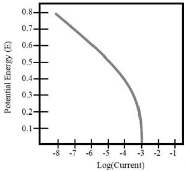
Figure description:
Potential Energy (E vs Log(Current
| Log(Current) | Potential Energy (E) |
|---|---|
| -8.0 | 0.79 |
| -7.0 | 0.69 |
| -6.0 | 0.59 |
| -5.0 | 0.49 |
| -4.0 | 0.37 |
| -3.5 | 0.29 |
| -3.1 | 0.10 |
| -3.0 | 0.00 |
Notes: The chart illustrates the relationship between Potential Energy (E and Log(Current. The Potential Energy decreases steadily as Log(Current increases from -8 to -4, followed by a sharper decline as Log(Current approaches -3.))))
FIGURE C-2. Tafel plot of a diffusion limited system.
When corrosion occurs, oxidation and reduction reactions occur simultaneously. The point at which the lines intersect can be used to determine the corrosion current () and the corrosion potential (). Figure C-3 illustrates this principle on an Evans diagram.
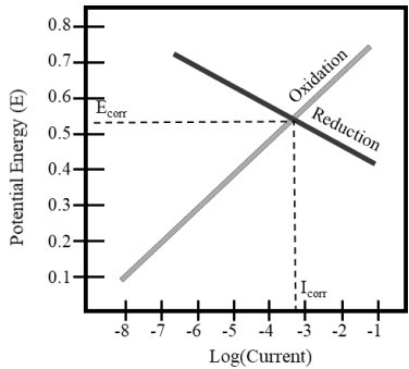
Figure description:
Corrosion Potential and Current Diagram
Potential Energy (E vs Log(Current
Legend
- Oxidation — color: Grey; symbol: Solid line
- Reduction — color: Dark Grey/Black; symbol: Solid line
Annotations
- Ecorr (horizontal_line - position: y = 0.54)
- Icorr (vertical_line - position: x = -3.2)
- Oxidation (text_label - position: next to the light grey line)
- Reduction (text_label - position: next to the dark grey line)
| Log(Current) | Oxidation Potential Energy (E) | Reduction Potential Energy (E) |
|---|---|---|
| -8.0 | 0.1 | null |
| -7.0 | 0.2 | null |
| -6.5 | null | 0.72 |
| -6.0 | 0.3 | 0.7 |
| -5.0 | 0.4 | 0.64 |
| -4.0 | 0.49 | 0.58 |
| -3.2 | 0.54 | 0.54 |
| -2.0 | 0.65 | 0.47 |
| -1.0 | 0.74 | 0.42 |
Notes: The chart illustrates an Evans diagram where the intersection of the oxidation (anodic and reduction (cathodic curves determines the corrosion potential (Ecorr and corrosion current (Icorr.))))
FIGURE C-3. Evans diagram with Ecorr and Icorr.
Since Evans diagrams are normally used for quantitative purposes, polarization curves can be used to collect data on a system of interest to determine its Ecorr and Icorr values. Figure C-4 shows the polarization curve with the Evans diagram overlaid on it. The linear slopes on the polarization Icorr . curves are extrapolated to where they intersect. This intersection point determines the Ecorr and
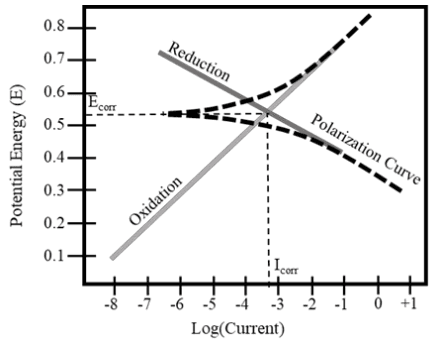
Figure description:
Potential Energy vs Log(Current
Potential Energy (E vs. Log(Current Polarization Diagram
Legend
- Reduction — color: grey; symbol: solid line
- Oxidation — color: grey; symbol: solid line
- Polarization Curve — color: black; symbol: dashed line
Annotations
- Ecorr (horizontal_line - position: y = 0.535)
- Icorr (vertical_line - position: x = -3.3)
| Log(Current) | Reduction (E) | Oxidation (E) | Polarization Curve (Upper (E)) | Polarization Curve (Lower (E)) |
|---|---|---|---|---|
| -8.0 | null | 0.09 | null | null |
| -7.0 | null | 0.20 | null | null |
| -6.5 | 0.72 | 0.25 | 0.535 | 0.535 |
| -6.0 | 0.69 | 0.30 | 0.537 | 0.533 |
| -5.0 | 0.63 | 0.40 | 0.545 | 0.525 |
| -4.0 | 0.58 | 0.50 | 0.565 | 0.505 |
| -3.3 | 0.535 | 0.535 | 0.585 | 0.485 |
| -3.0 | 0.520 | 0.565 | 0.600 | 0.475 |
| -2.0 | 0.460 | 0.660 | 0.670 | 0.440 |
| -1.0 | 0.405 | 0.755 | 0.760 | 0.380 |
| 0.0 | 0.345 | 0.850 | 0.850 | 0.315 |
| 1.0 | null | null | null | 0.240 |
Notes: The chart is a Tafel plot showing the intersection of reduction and oxidation kinetics at the corrosion potential (Ecorr and corrosion current (Icorr. The polarization curve deviates from the linear Tafel slopes near the intersection point.))
FIGURE C-4. Polarization curve with an Evans Diagram.
C.2.5 Mixed conductive material polarization curves. Traditionally, when applying the theory outlined in C.2.4 to mixed conductive materials, the polarization curves for two conductive materials are overlaid and the values at the point of intersection are determined to be the galvanic current and the galvanic potential. The established method of curve crossing worked as predicted for materials that have significantly different OCPs. However, materials that had
very close OCPs resulted in erroneous galvanic current values due to the extremely small current values near OCP where the materials’ curves crossed. Summation of the anodic scans of both materials and the cathodic scans of both materials allows for the elimination of the issue with close-OCP pairings, while not affecting the results from pairings that cross far from OCP. The intersection point of the anodic and cathodic portions of the galvanic curve is then determined to be the galvanic current and galvanic potential.
To verify this approach, two conductive materials of interest were joined together, ensuring electrical contact. A polarization curve on the joined conductive material couple was completed. The generated polarization curve of the joined materials was compared to the polarization curves produced using mixed potential theory. The results showed that both polarization curves had the same features at nearly the same Egal and Igal . In addition to this test, a zero resistance ammeter (ZRA) was performed on the same conductive materials. The ZRA confirmed these results by outputting a galvanic current and galvanic potential near where the mixed conductive materials curves intersect.
C.2.6 Accelerating factor determination. When coupling different conductive materials, the corrosion rate of the anodic member of a couple increases compared to the corrosion rate of the same conductive material if it was unpaired. The increase in corrosion rate can be quantified as the acceleration factor. To determine this, the corrosion rate of the anodic member in a galvanic couple is divided by the self-corrosion rate of the same anodic member. The summary of the acceleration factors is listed in Tables C-I, C-II and C-III.
C.2.7 Polarization control. The polarization of electrodes in an electrolyte solution occurs because a film of oxide, gas, or other compound changes the electrode surfaces. These changes reduce the potential difference relative to the open circuit potentials and lessen the corrosion rate. These changes on the surface increase the resistance of the external circuit and diminish current flow. They also tend to intensify or diminish with the change in galvanic current or applied current. Electrode polarization behavior is a means by which the compatibility of coupled dissimilar conductive materials in solution can be established. Polarization measurements can provide information as to the effects of relative areas of anode and cathode and effects of changes in potential on the corrosion.
Polarization of galvanic electrodes is illustrated on Figure C-5. When polarization mainly occurs at the anode, it is under anodic control. For a polarization reaction that occurs mainly at the cathode, the corrosion reaction is under cathodic control. If polarization reactions occur equally at both the anode and cathode, it is under mixed control. When the electrodes do not polarize, resistance of the circuit, the solution path (Re ) and the metallic portion (Rm ) control the reaction. Galvanic corrosion and current flow are polarization and resistance controlled.
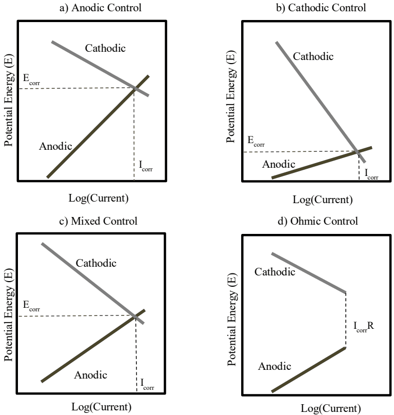
Figure description:
Types of Corrosion Control
a Anodic Control
Legend
- Anodic — color: Dark Brown; symbol: Solid line
- Cathodic — color: Grey; symbol: Solid line
Annotations
- E_corr (horizontal_line - position: y = 6.8)
- I_corr (vertical_line - position: x = 6.8)
| Log(Current) | Anodic Potential (E) | Cathodic Potential (E) |
|---|---|---|
| 1.0 | 1.0 | 9.0 |
| 6.8 | 6.8 | 6.8 |
| 9.0 | 9.0 | 6.0 |
b Cathodic Control
Legend
- Anodic — color: Dark Brown; symbol: Solid line
- Cathodic — color: Grey; symbol: Solid line
Annotations
- E_corr (horizontal_line - position: y = 3.2)
- I_corr (vertical_line - position: x = 6.8)
| Log(Current) | Anodic Potential (E) | Cathodic Potential (E) |
|---|---|---|
| 1.0 | 1.0 | 9.0 |
| 6.8 | 3.2 | 3.2 |
| 9.0 | 4.0 | 1.0 |
c Mixed Control
Legend
- Anodic — color: Dark Brown; symbol: Solid line
- Cathodic — color: Grey; symbol: Solid line
Annotations
- E_corr (horizontal_line - position: y = 5.0)
- I_corr (vertical_line - position: x = 7.4)
| Log(Current) | Anodic Potential (E) | Cathodic Potential (E) |
|---|---|---|
| 1.0 | 1.0 | 9.0 |
| 7.4 | 5.0 | 5.0 |
| 9.0 | 6.0 | 4.0 |
d Ohmic Control
Legend
- Anodic — color: Dark Brown; symbol: Solid line
- Cathodic — color: Grey; symbol: Solid line
Annotations
- I_corr R (vertical_line - position: x = 8.0, vertical gap between y = 4.0 and y = 6.0)
| Log(Current) | Anodic Potential (E) | Cathodic Potential (E) |
|---|---|---|
| 1.0 | 1.0 | 9.0 |
| 8.0 | 4.0 | 6.0 |
Notes: The charts are Evans diagrams showing different mechanisms of corrosion control. Potential Energy (E is plotted against Log(Current. The intersection of anodic and cathodic polarization curves identifies the corrosion potential (E_corr and corrosion current (I_corr. In ohmic control, a potential drop (I_corr*R exists between the anodic and cathodic reactions.)))))
FIGURE C-5. Types of polarization and control in galvanic corrosion.
C.2.8 Electrode areas. Under cathodic control, corrosion of the anode is proportional to the area of the cathode. If the cathode area is two to three times the area of the anode and if the polarization is negligible, the current is generally increased by the same factor. The same relationship prevails if the anode area is decreased relative to the cathode. Decreasing the area of the cathode, in effect increasing the area of the anode, reduces the galvanic current density and diminishes corrosion of the anode so that normal corrosion becomes dominant. The situation is somewhat different in mixed control. An increase in the cathode area can have some accelerating corrosion effect, but this is generally less than in the case of cathodic control, and the effect does not occur in a proportional way. General corrosion becomes less pronounced. In anodic control, the corrosion of the anode essentially is unaffected by the cathode area; increasing the area of the anode decreases the galvanic current.
C.2.9 Resistance and galvanic current. In a polarized galvanic circuit, resistance is contributed by the portion of the electrolyte between the anode and cathode (Re , internal path) and by the films of reaction products formed on the electrode surfaces (Rm , metallic path). These factors impede ion exchange and reduce current flow; therefore, the total resistance, R, of the circuit is expressed as R = Re + Rm . In the polarized system, as the resistance increases, the potentials of the anode and cathode approach each other until a steady state reaction is attained. The limiting current corresponds with the intersection of the polarization curves. This is the maximum current obtainable in the system if constant conditions are maintained.
C.2.10 The electrolyte medium. In each liquid medium or solution (for a given concentration of the electrolyte and temperature of the medium), a conductive material has a specific electrical potential. In a very corrosive solution, i.e., a solution having high conductivity and producing readily soluble compounds of the anode of a galvanic couple, the anode will corrode uniformly. If the cathode does not polarize, the corrosion of the anode will be accelerated. However, with polarization of the electrodes, galvanic current flow and corrosion subside. Generally, for a given electrolyte solution, the rate of corrosion decreases with higher concentration of the electrolyte or with lower temperature. In a solution containing ions that can polarize the anode, the cathode, or both, galvanic effects will be small. Coupled dissimilar conductive materials may exhibit different responses in the electrolyte solution because of pH changes. A conductive material, which is the anode in a neutral or acidic solution, may become the cathode if the solution is made basic.
This is illustrated with magnesium-aluminum couples in dilute, neutral, or slightly acidic sodium chloride solution. With dissolution of the magnesium anode, the solution becomes alkaline, and the aluminum is rendered anodic, a reversal of polarity. In a neutral sodium chloride solution, the anode iron of an iron-copper couple becomes the cathode when the solution is altered by the addition of ammonia.
C.2.11 Aeration, diffusion, and agitation of solution. Oxygen dissolved in the electrolyte solution can act to depolarize the cathode, and increase cathodic current. In some cases, oxygen may be necessary for oxidation of the anode. The amount of available oxygen and the rate of its diffusion can therefore change galvanic current. Ions, which are formed at the electrodes during galvanic corrosion, concentrate at or near the electrode surfaces (polarization) and impede current flow. For each of these cases in still solutions, the galvanic action is diffusion-dependent and is under diffusion control. Agitation or movement of the solution will increase the reaction rate. If the electrode areas are not large, little difference will ensue.
C.2.12 Importance of kinetics. Based on the previous definition of dissimilar conductive materials, it could be inferred that aluminum alloys would experience less corrosion when paired with stainless steels rather than titanium. This determination was based solely on the difference in the potentials – the difference in potential between aluminum and titanium is greater than the difference between aluminum and stainless steels. Under the previous method, smaller differences in potential indicated less propensity to corrode.
In comparison, when looking at the current of conductive materials in various sodium chloride concentrations, titanium is almost a magnitude lower in current than stainless steels. Although
39
the potential indicates that titanium is a worse pairing with aluminum, it takes a longer time for the corrosion to occur.
In practice, we see that aluminum alloys corrode at a slower rate when coupled with titanium than when coupled with stainless steels. This proves that even though the potential difference between the aluminum and titanium is not favorable, the kinetics show that it will take longer for the aluminum paired to the titanium to corrode compared to the stainless steel with the aluminum.
C.2.13 Calculating anode to cathode (A/C) ratio. To determine the desired A/C ratio for a galvanically incompatible conductive material couple, the equation listed in 5.5 shall be used. To use this equation, the galvanic corrosion rate for a selected conductive material couple shall be divided by 0.009 mil per year, which is the corrosion rate at which a galvanic conductive material couple is compatible. If the exact galvanic corrosion rate is not known, use the upper value of the corrosion rate rating. An example of this calculation is provided below.
Conductive Material Pair - : 1020 Steel with Inconel® 600 Corrosion Rating – 3 (1.0-4.99 mil/year) : <empty>

Figure description:
Mathematical equations for calculating the Anode to Cathode (A/C ratio:
- General Formula:
- Calculation with value:
- Result:
Anode to Cathode Ratio of 554.44:1
APPENDIX C
TABLE C-I. Accelerating factors of bare conductive materials in a 1:1A/C in immersed artificial seawater
| Cathodic Material | |||||||||||||||||||||||||||||||||||||||||||||||
|---|---|---|---|---|---|---|---|---|---|---|---|---|---|---|---|---|---|---|---|---|---|---|---|---|---|---|---|---|---|---|---|---|---|---|---|---|---|---|---|---|---|---|---|---|---|---|---|
| 1 | 2 | 3 | 4 | 5 | 6 | 7 | 8 | 9 | 10 | 11 | 12 | 13 | 14 | 15 | 16 | 17 | 18 | 19 | 20 | 21 | 22 | 23 | 24 | 25 | 26 | 27 | 28 | 29 | 30 | 31 | 32 | 33 | 34 | 35 | 36 | 37 | 38 | 39 | 40 | 41 | 42 | 43 | 44 | 45 | 46 | 47 | |
| 1. Mg EV31 | 2.0 | 12 | 15 | 77 | 66 | 167 | 30 | 6.9 | 1.3 | 259 | 219 | 630 | 640 | 774 | 61 | 505 | 511 | 687 | 236 | 19 | 12 | 1.6 | 65 | 116 | 248 | 134 | 114 | 1269 | 133 | 527 | 557 | 363 | 312 | 199 | 415 | 423 | 279 | 196 | 166 | 530 | 276 | 244 | 163 | 44 | 94 | 703 | |
| 2. Mg WE43 | 12 | 16 | 86 | 81 | 186 | 41 | 6.8 | 1.3 | 281 | 281 | 748 | 726 | 916 | 78 | 548 | 546 | 769 | 256 | 21 | 12 | 1.6 | 80 | 123 | 269 | 160 | 135 | 4239 | 143 | 596 | 697 | 395 | 340 | 207 | 465 | 475 | 320 | 217 | 190 | 598 | 332 | 283 | 190 | 55 | 100 | 726 | ||
| 3. Mg AZ31B | 7.2 | 104 | 67 | 218 | 8.9 | 5.7 | 1.6 | 340 | 170 | 526 | 605 | 636 | 54 | 590 | 584 | 677 | 315 | 14 | 18 | 2.2 | 70 | 170 | 319 | 152 | 133 | 2155 | 194 | 493 | 423 | 432 | 378 | 311 | 426 | 430 | 297 | 252 | 199 | 515 | 264 | 261 | 188 | 43 | 146 | 1080 | |||
| 4. Zinc | 40 | 4.5 | 54 | 6.8 | 25 | 8.9 | 222 | 42 | 261 | 327 | 382 | 8.9 | 403 | 219 | 327 | 190 | 44 | 29 | 25 | 41 | 58 | 109 | 56 | 42 | 7139 | 49 | 143 | 78 | 142 | 207 | 140 | 150 | 168 | 83 | 133 | 52 | 263 | 45 | 67 | 45 | 14 | 437 | 2027 | ||||
| 5. Zn-Ni Plated | 1.0 | 3.1 | 1.3 | 2.2 | 1.3 | 6.0 | 3.4 | 11 | 11 | 15 | 1.4 | 7.6 | 6.2 | 7.8 | 5.1 | 2.5 | 2.1 | 1.9 | 3.2 | 3.4 | 3.9 | 3.1 | 3.3 | 75 | 2.3 | 5.4 | 4.0 | 4.5 | 5.8 | 3.9 | 5.6 | 6.5 | 3.7 | 4.4 | 2.9 | 7.8 | 2.5 | 3.3 | 2.5 | 1.5 | 23 | 30 | |||||
| 6. Al5083 | 89.3 | 4.3 | 15 | 5.2 | 57 | 135 | 399 | 265 | 297 | 7.8 | 107 | 66 | 159 | 94 | 8.5 | 57 | 7.0 | 138 | 144 | 104 | 107 | 154 | 416 | 62 | 195 | 166 | 149 | 43 | 87 | 182 | 227 | 127 | 58 | 105 | 139 | 85 | 112 | 73 | 28 | 982 | 214 | ||||||
| 7. Cadmium | 1.0 | 1.2 | 1.0 | 1.7 | 2.5 | 5.8 | 4.3 | 7.5 | 1.1 | 2.5 | 2.7 | 3.2 | 2.3 | 1.1 | 1.7 | 1.1 | 2.5 | 2.6 | 2.2 | 2.2 | 2.7 | 12 | 1.7 | 3.1 | 2.8 | 2.6 | 1.7 | 2.0 | 3.0 | 3.5 | 2.4 | 1.8 | 2.1 | 2.7 | 1.9 | 2.2 | 1.8 | 1.3 | 12 | 4.2 | |||||||
| 8. Al6061 | 8.6 | 2.1 | 37 | 90 | 264 | 175 | 194 | 3.7 | 67 | 33 | 71 | 53 | 2.9 | 33 | 2.6 | 91 | 95 | 68 | 71 | 102 | 134 | 41 | 128 | 110 | 98 | 24 | 57 | 119 | 149 | 83 | 31 | 69 | 88 | 56 | 74 | 48 | 18 | 640 | 128 | ||||||||
| 9. CP Aluminum | 1.1 | 5.7 | 12 | 36 | 24 | 27 | 1.4 | 9.9 | 6.1 | 12 | 8.3 | 1.5 | 5.3 | 1.3 | 13 | 13 | 9.5 | 9.8 | 13.9 | 26 | 5.8 | 17 | 15 | 13 | 4.1 | 8.0 | 16 | 20 | 11 | 5.3 | 9.6 | 12 | 7.8 | 10 | 6.8 | 2.9 | 86 | 18 | |||||||||
| 10. A356 | 33 | 80 | 235 | 156 | 173 | 3.7 | 60 | 30 | 63 | 47 | 3.6 | 29 | 2.9 | 81 | 85 | 61 | 63 | 90 | 97 | 36 | 114 | 97 | 87 | 21 | 50 | 105 | 132 | 74 | 26 | 61 | 77 | 50 | 65 | 42 | 16 | 565 | 111 | ||||||||||
| 11. 1020 Steel | 3.3 | 8.1 | 5.7 | 7.0 | 1.1 | 3.0 | 2.7 | 3.9 | 2.6 | 1.1 | 1.9 | 1.1 | 3.2 | 3.3 | 2.6 | 2.7 | 3.4 | 7.4 | 1.9 | 4.1 | 3.7 | 3.4 | 1.7 | 2.3 | 3.9 | 4.7 | 3.0 | 2.0 | 2.6 | 3.2 | 2.3 | 2.7 | 2.1 | 1.4 | 18 | 4.6 | |||||||||||
| 12. Al7075 | 4.0 | 3.0 | 3.8 | 1.0 | 1.9 | 1.9 | 2.4 | 1.8 | 1.1 | 1.4 | 1.0 | 2.0 | 2.1 | 1.8 | 1.8 | 2.1 | 5.9 | 1.5 | 2.4 | 2.2 | 2.1 | 1.4 | 1.6 | 2.4 | 2.7 | 1.9 | 1.5 | 1.8 | 2.1 | 1.6 | 1.8 | 1.5 | 1.2 | 8.3 | 2.8 | ||||||||||||
| 13. A36 Steel | 1.7 | 1.8 | 1.0 | 1.3 | 1.2 | 1.4 | 1.2 | 1.0 | 1.1 | 1.0 | 1.3 | 1.3 | 1.2 | 1.3 | 1.4 | 2.2 | 1.1 | 1.5 | 1.4 | 1.3 | 1.1 | 1.2 | 1.4 | 1.5 | 1.3 | 1.1 | 1.2 | 1.3 | 1.2 | 1.3 | 1.2 | 1.1 | 3.4 | 1.5 | |||||||||||||
| 14. 1018 Steel | 2.1 | 1.0 | 1.4 | 1.4 | 1.7 | 1.4 | 1.0 | 1.2 | 1.0 | 1.5 | 1.5 | 1.4 | 1.4 | 1.6 | 3.0 | 1.2 | 1.7 | 1.6 | 1.5 | 1.2 | 1.3 | 1.7 | 1.8 | 1.5 | 1.2 | 1.4 | 1.5 | 1.3 | 1.4 | 1.3 | 1.1 | 4.7 | 1.8 | ||||||||||||||
| 15. 1008 Steel | 1.0 | 1.3 | 1.2 | 1.4 | 1.2 | 1.0 | 1.1 | 1.0 | 1.2 | 1.2 | 1.2 | 1.2 | 1.3 | 2.1 | 1.1 | 1.3 | 1.3 | 1.3 | 1.1 | 1.1 | 1.3 | 1.4 | 1.2 | 1.1 | 1.2 | 1.2 | 1.1 | 1.2 | 1.1 | 1.0 | 3.5 | 1.4 | |||||||||||||||
| 16. Al7050 | 26 | 13 | 36 | 23 | 1.8 | 15 | 1.5 | 35 | 37 | 27 | 28 | 39 | 90 | 16 | 50 | 43 | 38 | 11 | 22 | 46 | 58 | 33 | 14 | 27 | 35 | 22 | 29.0 | 19.1 | 7.7 | 247 | 53 | ||||||||||||||||
| 17. B7 Steel | 1.5 | 2.2 | 1.8 | 1.0 | 1.4 | 1.0 | 2.1 | 2.2 | 1.9 | 1.9 | 2.3 | 3.1 | 1.5 | 2.6 | 2.4 | 2.2 | 1.3 | 1.7 | 2.5 | 2.9 | 2.0 | 1.4 | 1.9 | 2.1 | 1.7 | 1.9 | 1.6 | 1.2 | 9.9 | 2.7 | |||||||||||||||||
| 18. MIL-11356 Steel | 3.3 | 2.5 | 1.0 | 1.8 | 1.0 | 3.2 | 3.3 | 2.6 | 2.6 | 3.5 | 5.6 | 1.9 | 4.3 | 3.7 | 3.4 | 1.5 | 2.3 | 4.0 | 4.9 | 3.0 | 1.7 | 2.6 | 3.2 | 2.2 | 2.7 | 2.0 | 1.3 | 20 | 4.4 | ||||||||||||||||||
| 19. 4340 Steel | 1.8 | 1.0 | 1.3 | 1.0 | 1.9 | 1.9 | 1.6 | 1.7 | 2.0 | 2.3 | 1.4 | 2.3 | 2.1 | 2.0 | 1.2 | 1.5 | 2.2 | 2.6 | 1.8 | 1.3 | 1.7 | 1.9 | 1.5 | 1.7 | 1.4 | 1.2 | 9.4 | 2.3 | |||||||||||||||||||
| 20. HY80 Steel | 1.0 | 1.5 | 1.0 | 2.5 | 2.6 | 2.1 | 2.2 | 2.7 | 2.7 | 1.7 | 3.2 | 2.8 | 2.6 | 1.4 | 1.9 | 3.0 | 3.5 | 2.4 | 1.5 | 2.1 | 2.4 | 1.9 | 2.2 | 1.8 | 1.3 | 13 | 3.1 | ||||||||||||||||||||
| 21. Tin | 67 | 1.6 | 376 | 381 | 265 | 285 | 427 | 5.3 | 53 | 123 | 119 | 128 | 19 | 46 | 95 | 168 | 75 | 9.3 | 76 | 127 | 54 | 72 | 43 | 69 | 2298 | 504 | |||||||||||||||||||||
| 22. Al2024 | 1.0 | 6.7 | 7.0 | 5.2 | 5.4 | 7.4 | 2.3 | 3.5 | 8.8 | 7.6 | 7.0 | 2.1 | 4.1 | 8.0 | 10 | 5.9 | 1.8 | 5.1 | 6.1 | 4.3 | 5.3 | 3.7 | 2.1 | 42 | 8.4 | ||||||||||||||||||||||
| 23. Ti-6Al-4V | 2227 | 710 | 1557 | 564 | 982 | 8.8 | 23.7 | 36 | 42 | 38 | 17 | 30 | 35 | 43 | 33 | 19 | 31 | 43 | 26 | 37 | 28 | 94 | 143 | 162 | |||||||||||||||||||||||
| 24. Brass, Yellow | 1.3 | 1.7 | 1.3 | 1.5 | 1.0 | 1.0 | 1.0 | 1.0 | 1.0 | 1.0 | 1.0 | 1.0 | 1.0 | 1.0 | 1.0 | 1.0 | 1.0 | 1.0 | 1.0 | 1.1 | 2.3 | 2.9 | |||||||||||||||||||||||||
| 25. Bronze | 3.2 | 1.8 | 2.5 | 1.0 | 1.0 | 1.0 | 1.1 | 1.0 | 1.0 | 1.0 | 1.0 | 1.1 | 1.0 | 1.0 | 1.0 | 1.1 | 1.0 | 1.0 | 1.0 | 1.2 | 3.8 | 6.9 | |||||||||||||||||||||||||
| 26. NiAl, C630 | 1.4 | 1.7 | 1.0 | 1.0 | 1.0 | 1.0 | 1.0 | 1.0 | 1.0 | 1.0 | 1.0 | 1.0 | 1.0 | 1.0 | 1.0 | 1.0 | 1.0 | 1.1 | 2.3 | 3.7 | |||||||||||||||||||||||||||
| 27. CuBe | 2.8 | 1.0 | 1.0 | 1.0 | 1.0 | 1.0 | 1.0 | 1.0 | 1.0 | 1.1 | 1.0 | 1.0 | 1.0 | 1.1 | 1.0 | 1.0 | 1.0 | 1.3 | 3.8 | 8.4 | |||||||||||||||||||||||||||
| 28. CP Copper | 1.0 | 1.0 | 1.0 | 1.0 | 1.0 | 1.0 | 1.0 | 1.0 | 1.0 | 1.0 | 1.0 | 1.0 | 1.0 | 1.0 | 1.0 | 1.1 | 2.5 | 4.9 | |||||||||||||||||||||||||||||
| 29. PH 13-8 | 2.2 | 3.6 | 5.3 | 3.6 | 2.1 | 3.8 | 3.5 | 3.5 | 3.0 | 3.9 | 2.4 | 3.5 | 2.1 | 3.2 | 2.5 | 12 | 18 | 73 | |||||||||||||||||||||||||||||
| 30. 304SS | 3.3 | 4.9 | 3.2 | 1.9 | 3.4 | 3.1 | 2.9 | 2.5 | 3.6 | 1.9 | 2.9 | 1.6 | 2.4 | 1.9 | 11 | 14 | 53 | ||||||||||||||||||||||||||||||
| 31. PH 15-5 | 2.7 | 2.0 | 1.4 | 2.0 | 1.9 | 1.8 | 1.7 | 2.1 | 1.4 | 1.8 | 1.2 | 1.6 | 1.4 | 5.3 | 7.6 | 26 | |||||||||||||||||||||||||||||||
| 32. 304SS Passivated | 1.6 | 1.2 | 1.6 | 1.5 | 1.5 | 1.4 | 1.6 | 1.2 | 1.4 | 1.1 | 1.3 | 1.2 | 3.3 | 4.9 | 16 | ||||||||||||||||||||||||||||||||
| 33. 410SS | 1.4 | 2.1 | 1.9 | 1.8 | 1.7 | 2.1 | 1.4 | 1.8 | 1.2 | 1.6 | 1.3 | 5.4 | 7.4 | 54 | |||||||||||||||||||||||||||||||||
| 34. Inconel ® 600 | 3.5 | 3.2 | 2.9 | 2.5 | 4.0 | 1.8 | 2.8 | 1.6 | 2.4 | 1.8 | 12 | 14 | 50 | ||||||||||||||||||||||||||||||||||
| 35. A286 Passivated | 1.9 | 1.7 | 1.6 | 2.1 | 1.3 | 1.7 | 1.2 | 1.5 | 1.3 | 4.9 | 6.3 | 19 | |||||||||||||||||||||||||||||||||||
| 36. PH 17-4 | 1.9 | 1.7 | 2.3 | 1.4 | 1.8 | 1.2 | 1.6 | 1.4 | 5.8 | 8.0 | 30 | ||||||||||||||||||||||||||||||||||||
| 37. 316SS | 1.8 | 2.6 | 1.4 | 1.9 | 1.2 | 1.6 | 1.3 | 6.6 | 7.8 | 26 | |||||||||||||||||||||||||||||||||||||
| 38. 316SS Passivated | 3.0 | 1.5 | 2.1 | 1.3 | 1.7 | 1.4 | 8.1 | 8.4 | 22 | ||||||||||||||||||||||||||||||||||||||
| 39. Monel ® 400 | 1.2 | 1.6 | 1.2 | 1.5 | 1.3 | 5.6 | 11 | 66 | |||||||||||||||||||||||||||||||||||||||
| 40. 410SS Passivated | 3.3 | 1.6 | 2.4 | 1.7 | 17 | 14 | 28 | ||||||||||||||||||||||||||||||||||||||||
| 41. A286 | 1.2 | 1.6 | 1.3 | 7.4 | 8.0 | 28 | |||||||||||||||||||||||||||||||||||||||||
| 42. PH 17-4 Passivated | 3.4 | 2.2 | 29 | 24 | 52 | ||||||||||||||||||||||||||||||||||||||||||
| 43. PH 13-8 Passivated | 1.5 | 13 | 11 | 24 | |||||||||||||||||||||||||||||||||||||||||||
| 44. PH 15-5 Passivated | 25 | 20 | 35 | ||||||||||||||||||||||||||||||||||||||||||||
| 45. Silver | 3.3 | 69 | |||||||||||||||||||||||||||||||||||||||||||||
| 46. Graphite | 4.6 | ||||||||||||||||||||||||||||||||||||||||||||||
| 47. Platnium | |||||||||||||||||||||||||||||||||||||||||||||||
| Cathodic Material | |||||||||||||||||||||||||||||||||||||||||||||||
| Anodic Material | a | b | c | d | e | f | g | h | i | j | k | l | m | n | |||||||||||||||||||||||||||||||||
| a. Mg WE43 T* | 1.8 | 1.8 | 11 | 5.9 | 14 | 9.3 | 8.4 | 8.5 | 10 | 17 | 9.8 | 11 | 19 | ||||||||||||||||||||||||||||||||||
| b. Mg EV31 T* | 1.5 | 12 | 5.2 | 31 | 8.8 | 7.7 | 9.1 | 9.8 | 99 | 10 | 11 | 432 | |||||||||||||||||||||||||||||||||||
| c. Mg AZ31B T* | 150 | 49 | 279 | 99 | 107 | 179 | 64 | 944 | 203 | 175 | 4938 | ||||||||||||||||||||||||||||||||||||
| d. Al5083 Cr+6 | 1.2 | 1.2 | 1.2 | 1.1 | 1.0 | 1.0 | 1.2 | 1.1 | 1.6 | 8.6 | |||||||||||||||||||||||||||||||||||||
| e. Al6061 Cr+6 | 2.1 | 2.1 | 1.7 | 1.3 | 1.3 | 2.8 | 2.9 | 5.3 | 30 | ||||||||||||||||||||||||||||||||||||||
| f. Al5083 Cr3+ | 2.1 | 1.8 | 2.1 | 1.5 | 3.7 | 3.2 | 3.3 | 3.6 | |||||||||||||||||||||||||||||||||||||||
| g. Al7075 Cr6+ | 1.8 | 1.2 | 1.1 | 2.4 | 1.3 | 3.1 | 29 | ||||||||||||||||||||||||||||||||||||||||
| h. Al6061 Cr+3 | 2.2 | 1.5 | 4.5 | 4.6 | 7.0 | 32 | |||||||||||||||||||||||||||||||||||||||||
| i. Cadmium w CC | 1.4 | 18 | 29 | 51 | 220 | ||||||||||||||||||||||||||||||||||||||||||
| j. Al7075 Cr+3 | 38 | 21 | 66 | 586 | |||||||||||||||||||||||||||||||||||||||||||
| k. Zn-Ni w CC | 2.6 | 4.1 | 17 | ||||||||||||||||||||||||||||||||||||||||||||
| l. Al2024 Cr6+ | 5.8 | 172 | |||||||||||||||||||||||||||||||||||||||||||||
| m. Al2024 Cr3+ | 74 | ||||||||||||||||||||||||||||||||||||||||||||||
| n. Electroless Ni | |||||||||||||||||||||||||||||||||||||||||||||||
| a. Mg WE43 T* | b. Mg EV31 T* | c. Mg AZ31B T* | d. Al5083 Cr+6 | e. Al6061 Cr+6 | f. Al5083 Cr3+ | g. Al7075 Cr6+ | h. Al6061 Cr+3 | i. Cadmium w CC | j. Al7075 Cr+3 | k. Zn-Ni w CC | l. Al2024 Cr6+ | m. Al2024 Cr3+ | n. Electroless Ni | ||||||||||||||||||||||||||||||||||
| 1. Mg EV31 | 3.2 | 1.3 | 1.3 | 25 | 9.9 | 67 | 18 | 17 | 7.8 | 28 | 133 | 20 | 28 | 248 | |||||||||||||||||||||||||||||||||
| 2. Mg WE43 | 3.2 | 4.1 | 3.8 | 99 | 30 | 273 | 65 | 62 | 24 | 118 | 500 | 73 | 118 | 835 | |||||||||||||||||||||||||||||||||
| 3. Mg AZ31B | 7.3 | 6.6 | 79 | 9.7 | 1.7 | 59 | 5.2 | 3.6 | 5.4 | 8.1 | 144 | 7.0 | 9.5 | 333 | |||||||||||||||||||||||||||||||||
| 4. Zinc | 10 | 10 | 112 | 1.3 | 2.1 | 2.6 | 3.5 | 3.6 | 18 | 3.1 | 26 | 12 | 12 | 59 | |||||||||||||||||||||||||||||||||
| 5. Zn-Ni Plated | 18 | 107 | 1493 | 5.6 | 19 | 17 | 18 | 1.1 | 1.3 | 1.0 | 2.0 | 1.5 | 1.5 | 2.7 | |||||||||||||||||||||||||||||||||
| 6. Al5083 | 15 | 44 | 460 | 1.0 | 1.3 | 1.5 | 1.2 | 1.5 | 2.4 | 1.7 | 11 | 13 | 22 | 96 | |||||||||||||||||||||||||||||||||
| 7. Cadmium | 19 | 262 | 3684 | 8.2 | 28 | 26 | 28 | 31 | 1.0 | 1.0 | 1.4 | 1.3 | 1.3 | 2.0 | |||||||||||||||||||||||||||||||||
| 8. Al6061 | 10 | 10 | 70 | 1.0 | 1.5 | 2.6 | 1.3 | 2.9 | 1.3 | 1.1 | 5.2 | 4.7 | 11 | 63 | |||||||||||||||||||||||||||||||||
| 9. CP Aluminum | 8.3 | 9.5 | 221 | 1.7 | 4.4 | 5.1 | 4.2 | 6.0 | 27 | 1.0 | 1.9 | 2.0 | 2.6 | 8.8 | |||||||||||||||||||||||||||||||||
| 10. A356 | 1.7 | 2.0 | 58 | 1.0 | 1.5 | 2.7 | 1.3 | 3.2 | 5.0 | 12 | 5.2 | 4.7 | 9.3 | 56 | |||||||||||||||||||||||||||||||||
| 11. 1020 Steel | 20 | 503 | 8913 | 5.3 | 18 | 17 | 17 | 20 | 127 | 343 | 1.2 | 1.3 | 1.4 | 2.5 | |||||||||||||||||||||||||||||||||
| 12. Al7075 | 17 | 66 | 998 | 12 | 43 | 39 | 42 | 46 | 311 | 844 | 1.1 | 1.1 | 1.2 | 1.7 | |||||||||||||||||||||||||||||||||
| 13. A36 Steel | 20 | 746 | 8655 | 37 | 127 | 116 | 123 | 136 | 918 | 2492 | 69 | 1.0 | 1.1 | 1.2 | |||||||||||||||||||||||||||||||||
| 14. 1018 Steel | 20 | 991 | 12267 | 24 | 84 | 77 | 82 | 90 | 608 | 1651 | 46 | 1.0 | 1.1 | 1.3 | |||||||||||||||||||||||||||||||||
| 15. 1008 Steel | 21 | 1045 | 11930 | 27 | 94 | 86 | 90 | 101 | 680 | 1821 | 51 | 1.0 | 1.0 | 1.2 | |||||||||||||||||||||||||||||||||
| 16. Al7050 | 13 | 26 | 190 | 1.0 | 1.9 | 2.9 | 1.7 | 3.5 | 13 | 26 | 1.7 | 3.1 | 5.8 | 25 | |||||||||||||||||||||||||||||||||
| 17. B7 Steel | 21 | 1021 | 16494 | 9.5 | 33 | 30 | 31 | 36 | 245 | 629 | 19 | 1.1 | 1.2 | 1.8 | |||||||||||||||||||||||||||||||||
| 18. MIL-11356 Steel | 20 | 957 | 11432 | 5.0 | 17 | 15 | 15 | 19 | 146 | 303 | 11 | 1.1 | 1.2 | 2.4 | |||||||||||||||||||||||||||||||||
| 19. 4340 Steel | 20 | 1205 | 15537 | 10 | 35 | 31 | 32 | 40 | 331 | 644 | 24 | 1.0 | 1.1 | 1.6 | |||||||||||||||||||||||||||||||||
| 20. HY80 Steel | 20 | 459 | 8244 | 7.5 | 26 | 23 | 24 | 29 | 210 | 490 | 16 | 1.1 | 1.2 | 2.0 | |||||||||||||||||||||||||||||||||
| 21. Tin | 12 | 17 | 334 | 1.0 | 1.8 | 3.0 | 1.2 | 3.7 | 14 | 11 | 1.6 | 2.0 | 2.8 | 46 | |||||||||||||||||||||||||||||||||
| 22. Al2024 | 16 | 32 | 845 | 4.2 | 15 | 7.2 | 12 | 18 | 130 | 257 | 9.9 | 1.0 | 1.1 | 4.6 | |||||||||||||||||||||||||||||||||
| 23. Ti-6Al-4V | 2.4 | 3.1 | 113 | 1.0 | 1.5 | 2.9 | 1.2 | 3.4 | 9.6 | 9.8 | 1.4 | 1.6 | 1.1 | 4.3 | |||||||||||||||||||||||||||||||||
| 24. Brass, Yellow | 16 | 61 | 920 | 13 | 44 | 22 | 43 | 47 | 317 | 861 | 24 | 349 | 256 | 37 | |||||||||||||||||||||||||||||||||
| 25. Bronze | 19 | 215 | 3036 | 13 | 46 | 8.4 | 44 | 49 | 331 | 899 | 25 | 365 | 268 | 12 | |||||||||||||||||||||||||||||||||
| 26. NiAl, C630 | 20 | 413 | 5566 | 9.4 | 33 | 16 | 32 | 35 | 239 | 641 | 18 | 255 | 185 | 26 | |||||||||||||||||||||||||||||||||
| 27. CuBe | 18 | 138 | 1974 | 9.7 | 34 | 6.8 | 33 | 36 | 246 | 664 | 19 | 268 | 197 | 9.8 | |||||||||||||||||||||||||||||||||
| 28. CP Copper | 17 | 111 | 1351 | 14 | 49 | 11 | 47 | 52 | 353 | 960 | 26 | 390 | 289 | 17 | |||||||||||||||||||||||||||||||||
| 29. PH 13-8 | 21 | 2677 | 26582 | 10 | 36 | 3.4 | 24 | 59 | 694 | 663 | 50 | 36 | 8.9 | 1.0 | |||||||||||||||||||||||||||||||||
| 30. 304SS | 19 | 247 | 3430 | 5.6 | 20 | 3.4 | 19 | 21 | 142 | 383 | 11 | 141 | 77 | 1.2 | |||||||||||||||||||||||||||||||||
| 31. PH 15-5 | 20 | 676 | 7417 | 18 | 61 | 3.4 | 59 | 66 | 447 | 1203 | 33 | 403 | 204 | 1.5 | |||||||||||||||||||||||||||||||||
| 32. 304SS Passivated | 19 | 465 | 4527 | 15 | 53 | 3.4 | 50 | 56 | 382 | 1030 | 29 | 343 | 178 | 1.6 | |||||||||||||||||||||||||||||||||
| 33. 410SS | 20 | 632 | 8646 | 14 | 47 | 3.4 | 46 | 51 | 343 | 925 | 26 | 333 | 186 | 1.5 | |||||||||||||||||||||||||||||||||
| 34. Inconel ® 600 | 20 | 632 | 8646 | 3.2 | 11 | 3.4 | 9.8 | 13 | 97 | 205 | 7.4 | 61 | 29 | 1.5 | |||||||||||||||||||||||||||||||||
| 35. A286 Passivated | 20 | 521 | 7636 | 7.7 | 27 | 3.4 | 26 | 29 | 198 | 523 | 15 | 154 | 69 | 1.1 | |||||||||||||||||||||||||||||||||
| 36. PH 17-4 | 20 | 513 | 8543 | 16 | 57 | 3.4 | 54 | 61 | 417 | 1111 | 31 | 343 | 160 | 1.3 | |||||||||||||||||||||||||||||||||
| 37. 316SS | 20 | 555 | 6723 | 20 | 71 | 3.4 | 68 | 76 | 521 | 1396 | 39 | 482 | 259 | 1.5 | |||||||||||||||||||||||||||||||||
| 38. 316SS Passivated | 20 | 563 | 6911 | 11 | 40 | 3.4 | 38 | 43 | 291 | 776 | 22 | 246 | 118 | 1.7 | |||||||||||||||||||||||||||||||||
| 39. Monel ® 400 | 19 | 317 | 3900 | 3.8 | 13 | 3.4 | 10 | 17 | 129 | 228 | 9.8 | 32 | 12 | 1.4 | |||||||||||||||||||||||||||||||||
| 40. 410SS Passivated | 20 | 319 | 5141 | 9.5 | 33 | 3.4 | 32 | 35 | 240 | 648 | 18 | 224 | 115 | 1.1 | |||||||||||||||||||||||||||||||||
| 41. A286 | 19 | 195 | 2504 | 12 | 41 | 3.4 | 39 | 45 | 315 | 806 | 24 | 285 | 165 | 1.4 | |||||||||||||||||||||||||||||||||
| 42. PH 17-4 Passivated | 20 | 756 | 9617 | 7.7 | 27 | 3.4 | 26 | 29 | 194 | 523 | 15 | 175 | 85 | 1.7 | |||||||||||||||||||||||||||||||||
| 43. PH 13-8 Passivated | 19 | 236 | 2633 | 10 | 35 | 3.4 | 34 | 38 | 258 | 688 | 19 | 217 | 106 | 1.3 | |||||||||||||||||||||||||||||||||
| 44. PH 15-5 Passivated | 19 | 260 | 3201 | 6.6 | 23 | 3.4 | 22 | 25 | 168 | 445 | 13 | 138 | 64 | 1.5 | |||||||||||||||||||||||||||||||||
| 45. Silver | 19 | 176 | 2280 | 2.5 | 8.7 | 3.4 | 8.4 | 9.4 | 63 | 171 | 5.0 | 69 | 50 | 1.3 | |||||||||||||||||||||||||||||||||
| 46. Graphite | 15 | 39 | 574 | 87 | 304 | 3.5 | 290 | 326 | 2234 | 5982 | 166 | 2369 | 1719 | 2.8 | |||||||||||||||||||||||||||||||||
| 47. Platnium | 21 | 231 | 5646 | 17 | 58 | 3.5 | 56 | 65 | 469 | 1149 | 35 | 448 | 331 | 6.5 | |||||||||||||||||||||||||||||||||
TABLE C-II. Accelerating factors of treated conductive materials in a 1:1A/C in immersed artificial seawater
42
APPENDIX C
TABLE C-III. Accelerating factors of bare versus treated conductive materials in a 1:1 A/C in immersed artificial seawater
43
CONCLUDING MATERIAL
Custodians: Navy – AS Air Force – 20 Army – MR
Preparing activity: Navy - AS Project: MFFP-2020-011
Review activities: Navy – MC, SH Air Force – 19, 184
NOTE: The activities listed above were interested in this document as of the date of this document. Since organizations and responsibilities can change, you should verify the currency of the information above using the ASSIST Online database at https://assist.dla.mil.
44